24
5 Measurements
5.1 Insulation resistance (R
ISO
)
Insulation resistance measurement is performed in order to assure safety against electric shock.
Using this measurement the following items can be determined:
- Insulation resistance between installation conductors and protective conductor/earth
- Insulationresistanceofnon-conductiverooms(wallsandoors)
- Insulation resistance of earth cables
- Resistanceofsemi-conductive(antistatic)oors
How to perform insulation resistance measurement:
Step 1 Select the R
ISO
, ISOLATION/ INSULATION function with the function selector switch. The
following menu is displayed:
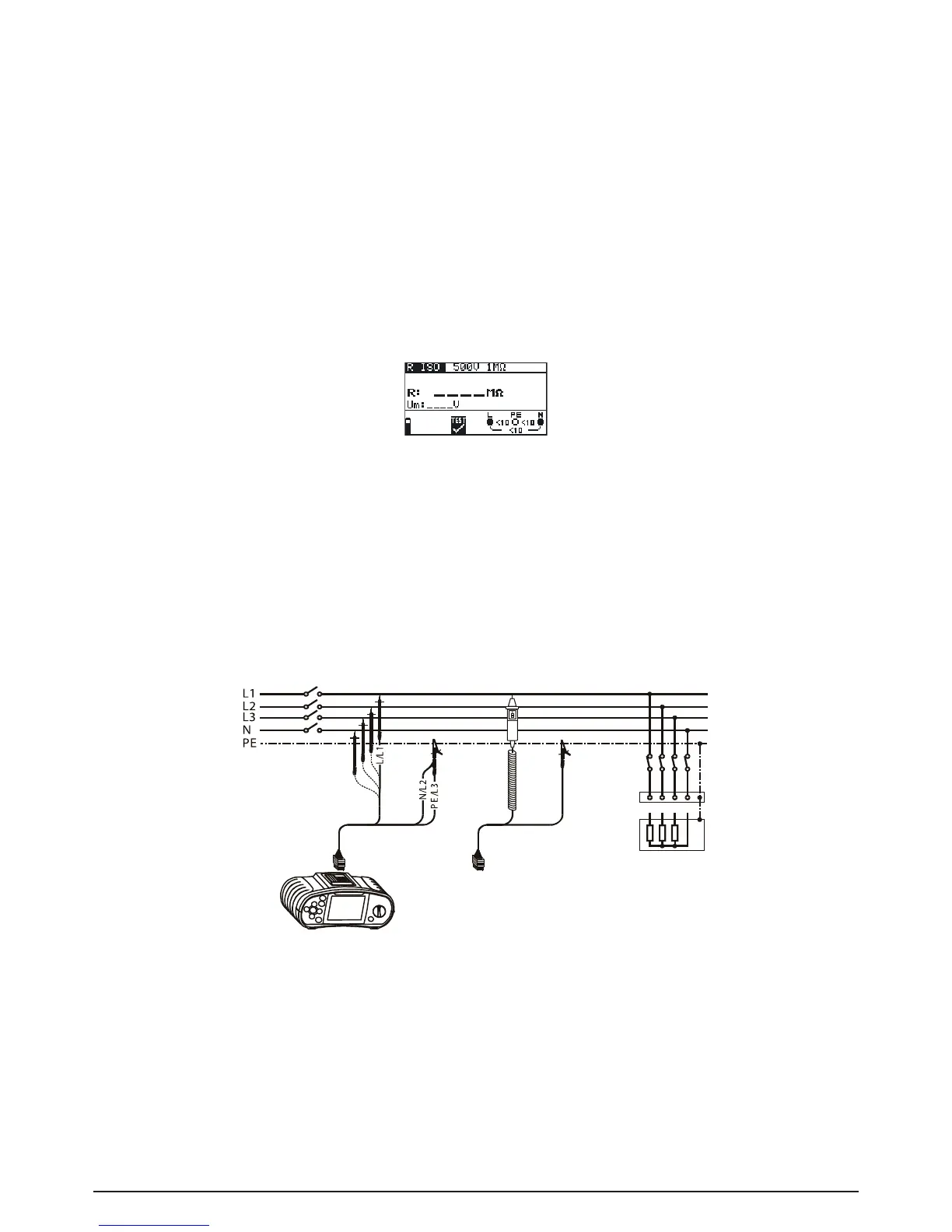
Fig. 5.1: Insulation resistance measurement menu
Connect the test cable to the BENNING IT 110/ BENNING IT 120 B.
Step 2 Set the following measuring parameters and limit values:
- Nominal test voltage
- Low limit resistance value
Step 3 Connecttestcabletotheitemundertest.Followtheconnectiondiagramshowningure
5.2 to perform insulation resistance measurement. Use the Help function if necessary.
Fig. 5.2: Connection of universal test cable and tip commander
Step 4 Check the displayed warnings and online voltage/terminal monitor before starting the
measurement. If OK, press and hold the TEST key until result is stabilised. Actual mea-
sured results are shown on the display during measurement.
After the TEST key is released the last measured results are displayed, together with
the PASS/FAIL indication (if applicable).