44
How to test the PE terminal:
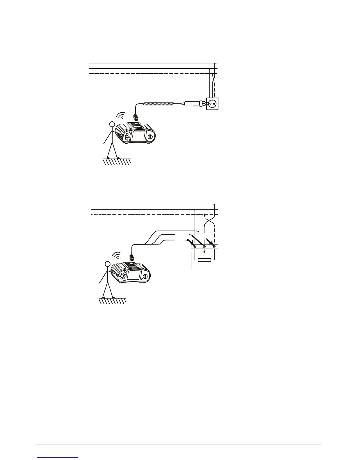
Step 1 Connect the test cable to the BENNING IT 110/ BENNING IT 120 B.
Step 2 Followtheconnectiondiagramsingures5.42and5.43totestthePEterminal.
Fig. 5.43: Connection of universal test cable to load connection
terminals with reversed L and PE conductors
Step 3 Touch the PE test probe (TEST key) for a few seconds. If the PE terminal is connected
to phase voltage, a warning note is displayed and the instrument buzzer activated.
Warning:
- If phase voltage is detected on the tested PE terminal, stop all measurements immediately and
take care that the fault is eliminated before proceeding with any activity.
Note:
- The PE terminal can only be tested when the function selector switch is set as follows: Z
l/Ik
(L-
N/ L); Z
s/Ik
(L/ PE); FI/ RCD TEST.
- For correct testing of the PE terminal, the TEST key has to be touched for a few seconds.
- Makesuretostandonanon-isolatedoorwhilecarryingoutthetest,otherwisethetestresult
may be wrong.