26
Connect the test cable to the BENNING IT 110/ BENNING IT 120 B.
Step 2 Set the following limit value:
- High limit resistance value
Step 3 BeforeperformingthelowΩmeasurement,compensatetestleadresistanceasfollows:
1. Shorttestleadrstasshowningure5.5.
Fig. 5.5: Shorted test leads
2. PresstheTESTkeyinordertoperformregularmeasurement.Resultcloseto0.00Ωis
displayed.
3. Press the CAL key. After performing test lead compensation, the compensated test lead indica-
tor (Co) is displayed.
4. In order to annul potential compensation follow the procedure described in this step with open
test leads. After annulling compensation, the compensation indicator disappears.
Compensation performed in this function is also considered in the Continuity measurement.
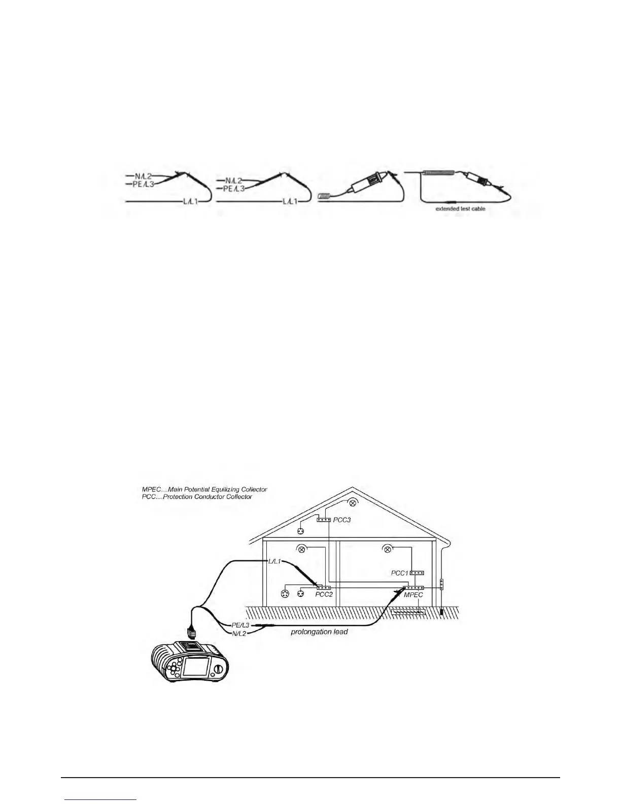
Step 4 Connecttestcabletotheitemundertest.Followtheconnectiondiagramshownin-
gures 5.6 and 5.7 to perform LowΩresistance measurement. Use the Help function if
necessary..
Fig. 5.6: Connection of universal test cable and optional probe test lead (extension)