35
Connect the test cable to the BENNING IT 110/ BENNING IT 120 B.
Step 2 Set the following measuring parameters:
- Nominal differential trip-out current
- RCD type
Step 3 Followtheconnectiondiagramshowningure5.15(seethechapterContact voltage)
to perform the RCD autotest. Use the Help function if necessary.
Step 4 Check the displayed warnings and online voltage/terminal monitor before starting the
measurement. If OK, press the TEST key. The autotest sequence starts to run as follows:
1. Trip-out time measurement with the following measurement parameters:
- Test current ½×I
∆N
- Test current started with the positive half-wave at 0°
Measurement does not normally trip an RCD. The following menu is displayed:
Fig. 5.22: Step 1 RCD autotest results
After performing step 1 the RCD autotest sequence automatically proceeds with step 2.
2. Trip-out time measurement with the following measurement parameters:
- Test current ½×I
∆N
- Test current started with the negative half-wave at 180°
Measurement does not normally trip an RCD. The following menu is displayed:
Fig. 5.23: Step 2 RCD autotest results
After performing step 2 the RCD autotest sequence automatically proceeds with step 3.
3. Trip-out time measurement with the following measurement parameters:
- Test current I
∆N
- Test current started with the positive half-wave at 0°
Measurement normally trips an RCD within allowed time period. The following menu is displayed:
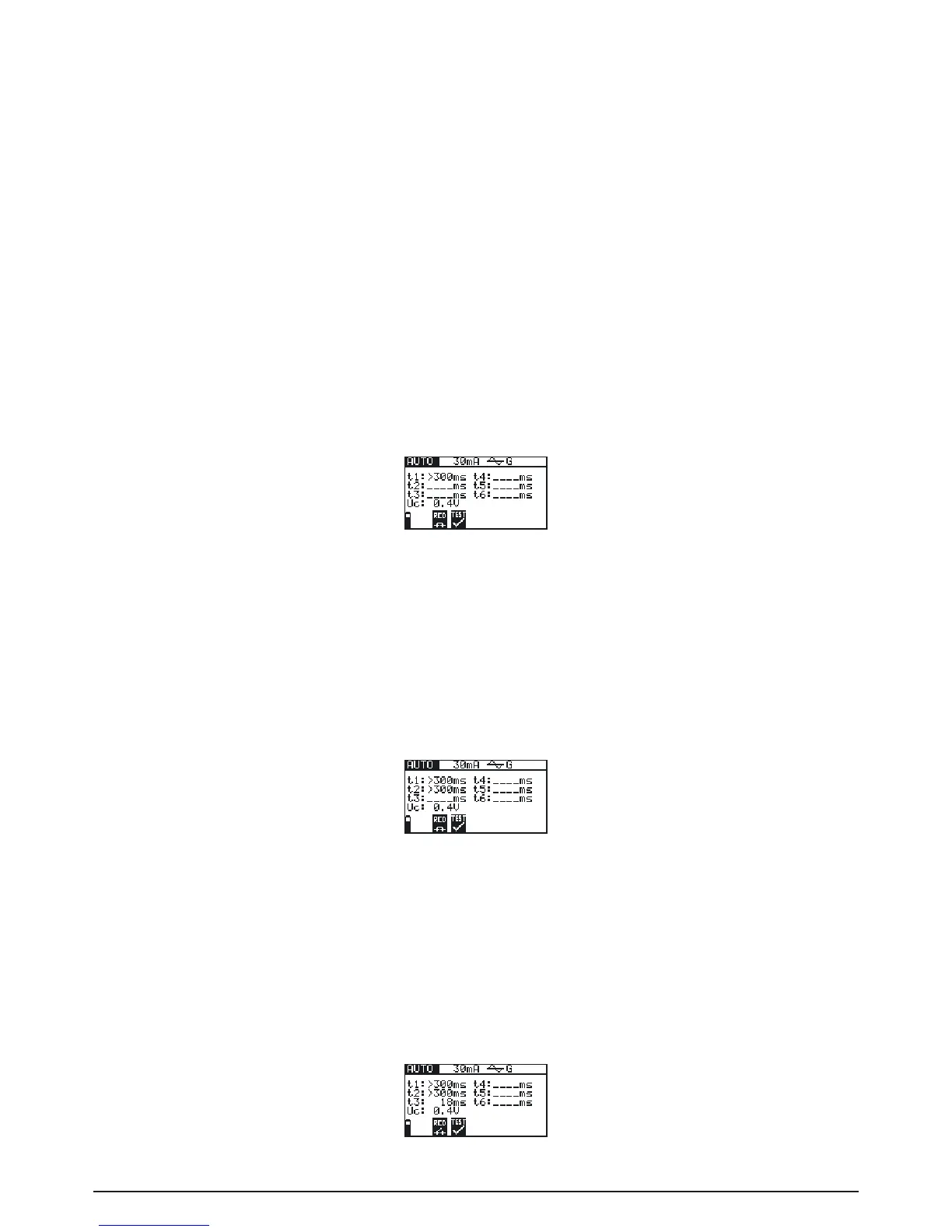
Fig. 5.24: Step 3 RCD autotest results