38
Connect the test cable to the BENNING IT 110/ BENNING IT 120 B.
Step 2 Set the following measuring parameters:
- Fuse type
- Fuse current rating
- Fuse trip-out time
Appendix A contains a list of different fuse types.
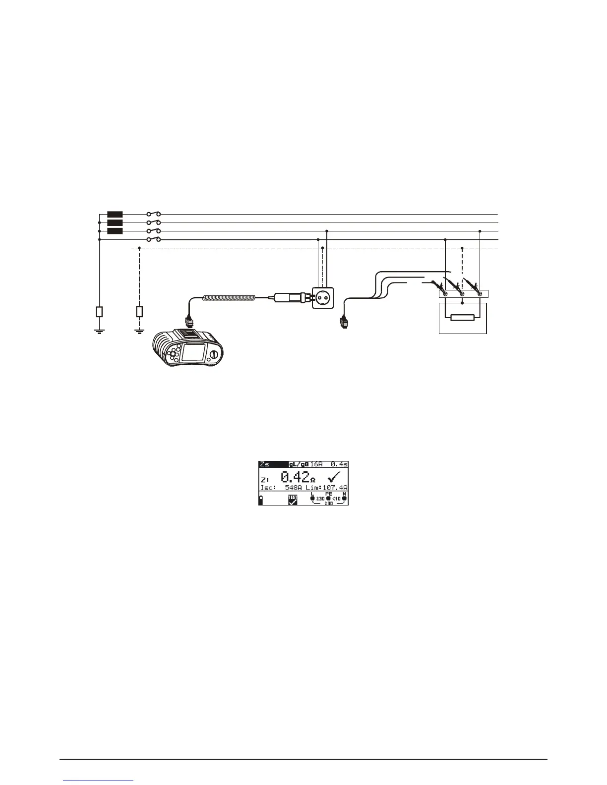
Step 3 Followtheconnectiondiagramshowningure5.29toperformloopimpedancemeasu-
rement. Use the Help function if necessary.
Fig. 5.29 Connection of plug cable and universal test cable
Step 4 Check the displayed warnings and online voltage/terminal monitor before starting the
measurement. If OK, press the TEST key. After performing, the measurement results
appear on the display together with the PASS/FAIL indication (if applicable).
Fig. 5.30: Example of loop impedance measurement results
Displayed results:
Z: Loop impedance
I
SC
: Prospective short-circuit current
Lim: Low limit of prospective short-circuit current value
Save displayed results for documentation purposes. Refer to chapter 6.1 for further information on
setting functions and saving of measurement results (BENNING IT 120 b only).
Note:
- L and N test terminals are reversed automatically if L/L1 and N/L2 test leads (universal test
cable) are connected in reversed way, or terminals of the tested wall plug are reversed, or plug
commander is turned around.
- Thespeciedaccuracyoftestedparametersisvalidonlyifthemainsvoltageisstableduring
the measurement.
- The low limit prospective short-circuit current value depends on fuse type, fuse current rating,
fuse trip-out time and I
PSC
scaling factor.