48
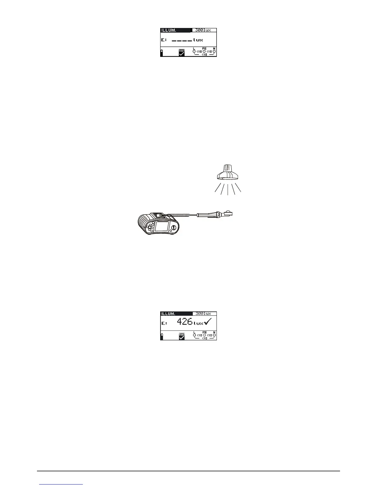
Fig. 5.50: Illumination measurement menu
Connect the luxmeter probe to the instrument.
Step 2 Set the following limit value:
- Low limit illumination value
Step 3 Turn on the luxmeter probe (ON/OFF key, green LED is lit). Position the luxmeter probe
in such a way that the measured light falls in parallel onto the light sensor. Follow the
connectiondiagramshowningure5.51toperformilluminationmeasurement.Usethe
Help function if necessary.
Fig. 5.51: Correct luxmeter probe positioning
Step 4 Check the displayed warnings before starting measurement. If OK, press the TEST key
to start the measurement. Actual measuring result with PASS/FAIL indication (if appli-
cable) is shown on the display during measurement.
To stop measurement at any time press the TEST key again. The last measured result is
displayed, together with the PASS/FAIL indication (if applicable).
Fig. 5.52: Example of illumination measurement result
Displayed results:
E: Illumination
Save displayed results for documentation purposes. Refer to chapter 6.1 for further information on
setting functions and saving of measurement results. (BENNING IT 120 B only).
Note:
- Shadow and irregular incidence affect the measurement result!