11
2 - TECHNICAL SPECIFICATIONS
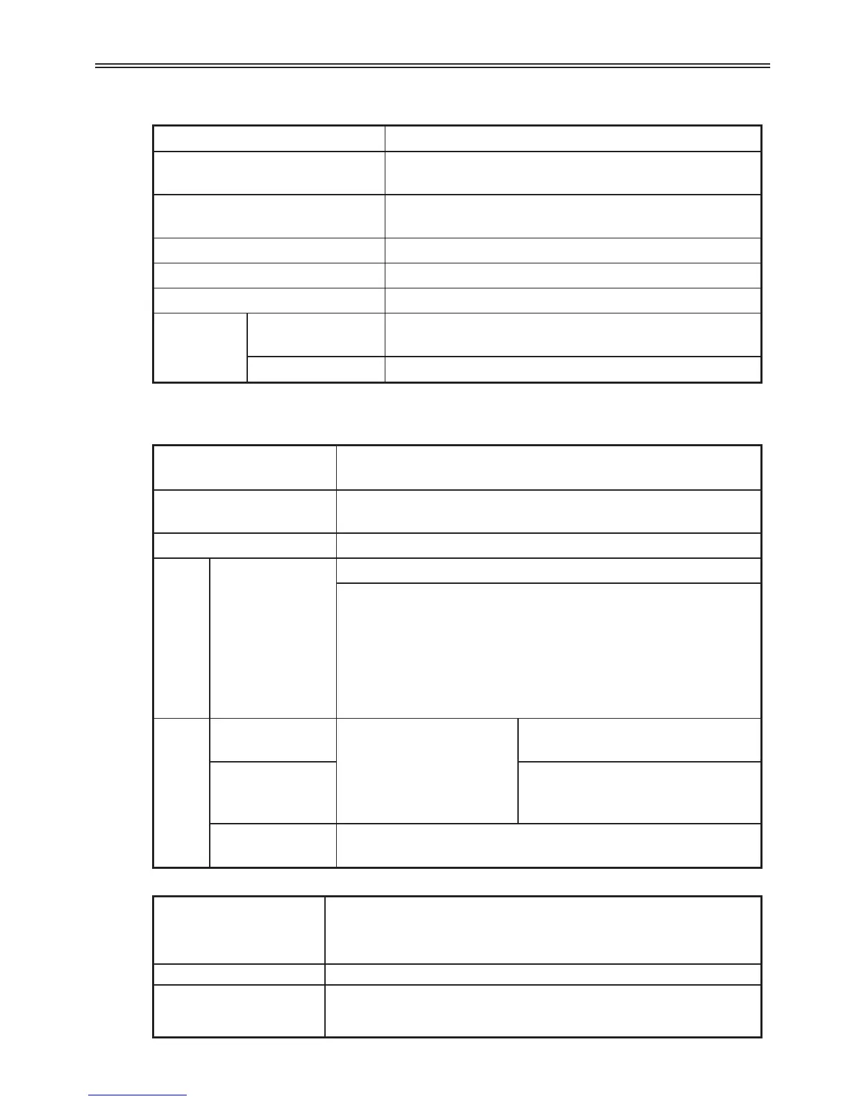
Control Method V/F, Sensorless vector control
Frequency Setting Resolution
Digital command: 0.01Hz
Analog command: 0.06Hz (Max freq.: 60Hz)
Frequency Accuracy
Digital command: 0.01% of Max output frequency
Analog command: 0.1% of Max output frequency
V/F Pattern Linear, Squared, User V/F
Overload Capacity 150% per 1 min.
Torque Boost Manual/Auto torque boost
Dynamic
Braking
Max braking
torque
20%
1)
Time / %ED 150%
2) when using optional DB resistor
1) Means average braking torque during Decel to stop of a motor.
2) Refer to Chapter 9 for DB resistor specification.
Control
Operation Mode
Keypad/ Terminal/ Communication option/ Remote keypad
selectable
Frequency Setting
Analog: 0 ~ 10[V], -10 ~ 10[V], 0 ~ 20[mA]
Digital: Keypad
Operation Features PID, Up-down, 3-wire
Input
Multi-function
terminal
P1~P8
NPN / PNP selectable (See page 3-6)
FWD/REV RUN, Emergency stop, Fault reset,
Jog operation, Multi-step Frequency-High, Mid, Low,
Multi-step, Accel/Decel-High, Mid, Low, DC braking at stop,
2
nd
motor select, Frequency UP/Down, 3-wire operation,
External trip A, B, PID-drive (v/f) operation bypass,
Option-drive (v/f) operation bypass, Analog Hold,
Accel/Decel stop
Output
Open collector
terminal
Fault output and drive
status output
Less than DC 24V 50mA
Multi-function
relay
(N.O., N.C.)
Less than AC250V 1A,
Less than DC 30V 1A
Analog output
0 - 10 Vdc (less than10mA): Output Freq, Output Current,
Output Voltage, DC link selectable
Operation
Trip
Over Voltage, Under Voltage, Over Current, Ground Fault current
detection, drive Overheat, Motor Overheat, Output Phase Open,
Overload Protection, Communication Error, Loss of Speed
Command, Hardware Fault, Fan trip
Alarm Stall prevention, overload
Momentary Power Loss
Below 15 msec: Continuous operation (should be within rated input
voltage, rated output power.)
Above 15 msec: Auto restart enable
Protection Function
 Loading...

