Power Terminals
3.5 Power Terminals
24
3 - RECEIVING AND INSTALLATION
R
S
T
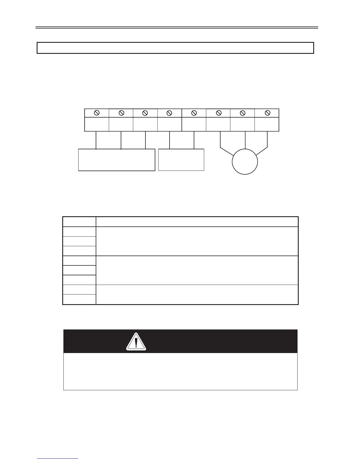
B1
B2
U
V
W
DB
Resistor
3 Power Input: R,S,T
1 Power Input: R,T
f
f
Figure : RSi GX Power Terminals
Symbol Description
R
AC Line Input Terminal
3(1) phase, 200-230V AC for 200V class units and 380-460V AC for
400V class units. 1 Phase input terminals: R and T
S
T
U
3 Phase Power Output Terminals to Motor
V
W
B1
Dynamic Braking Resistor Connection Terminal
B2
Normal stray capacitance between drive chassis and the power devices
inside the drive and AC line can provide a high impedance shock hazard.
Do not apply power to the drive if the drive frame (Power terminal G) is
not grounded.
WARNING
 Loading...

