3.6.4
Power and Motor Connection
31
3 - RECEIVING AND INSTALLATION
Drive Capacity
Terminal
Screw
Size
Screw
Torque
1)
Kgfcm /
lb-in
Grounding
Method
Wire
2)
mm
2
AWG
R,S,T U,V,W R,S,T U,V,W
2
0
0
V
1.0HP M3 10/8.7
Type 3
2 2 14 14
2.0HP M3 10/8.7 2 2 14 14
3.0HP M3 15/13 2 2 14 14
5.0HP M3 15/13 3.5 3.5 12 12
4
0
0
V
1.0HP M3 10/8.7
Special
Type 3
2 2 14 14
2.0HP M3 15/13 2 2 14 14
3.0HP M3 15/13 2 2 14 14
5.0HP M3 15/13 2 2 14 14
1) Apply the rated torque to terminal screws. Loose terminal screws can cause a short circuit or
other malfunction. Over tightening the terminal screws/bolts may permanently damage the
terminals.
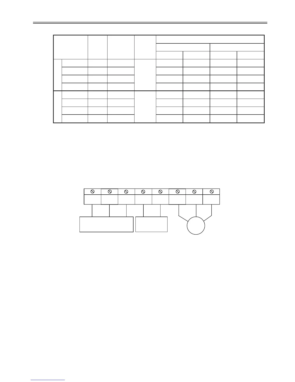
Motor should be connected to the
U,V,W terminals.
If the forward swich (FX) is on, the
motor should rotate counter clockwise
when viewed rom the load side of the
motor. If the mtor rotates in the reverse
direction, switch the U and V terminals.
Power supply must be connected o
the R,ST terminals.
Connecting it to the U,V,W terminals
causes internal damages to the drive
Arrangng the phase sequence is not
necessary.
R
S
T
B1
B2
U
V
W
DB
Resistor
3 Power Input: R,S,T
1 Power Input: R,T
f
f
 Loading...

