138
7 - PARAMETER DESCRIPTION
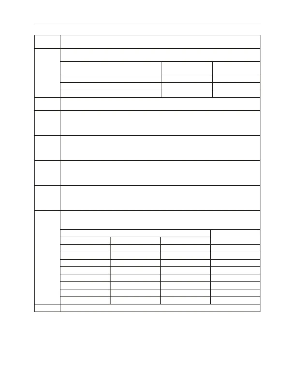
Bits 4, 5, 6
of Seq Cntl
Description of Seq Count Function (Bits 4, 5, 6)
000
Time Base - The current sequencer state will last for a time interval equal to the number “Seq
Count X” multiplied by the time base congured in the Seq Appl (APP 01) parameter.
Seq Appl Setting
Time to
Advance
Max Seq Time
1 sec Base (1 sec) * (Seq Cnt X)
18.2 hours
0.1 sec Base (0.1 sec) * (Seq Cnt X)
1.82 hours
0.01 sec Base (0.01 sec) * (Seq Cnt X)
10.92 minutes
001
Pulse Count - The current sequencer state will last until the number of pulses programmed into “Seq
Count X” is detected on terminal Vin1.
010
Low Analog Voltage Threshold - The active sequencer state lasts until the voltage signal applied to
terminal Vin2 is < a value programmed into “Seq Count X”. The value programmed into “Seq Count
X” should be the percentage of input after span and offset are applied (where 100.00% = 10000).
NOTE:The % of analog input after span and offset can be read in parameter I/O39(Vin2 Stat)
011
High Analog Voltage Threshold - The active sequencer state lasts until the voltage signal applied to
terminal Vin2 is > a value programmed into “Seq Count X”. The value programmed into “Seq Count
X” should be the percentage of input after span and offset are applied (where 100.00% = 10000).
NOTE:The % of analog input after span and offset can be read in parameter I/O39(Vin2 Stat)
100
Low Analog Current Threshold - The active sequencer state lasts until the current signal applied to
Cin terminals is < a value programmed into “Seq Count X”. The value programmed into “Seq Count
X” should be the percentage of input after span and offset are applied (where 100.00% = 10000).
NOTE:The % of analog input after span and offset can be read in parameter I/O39(Vin2 Stat)
101
High Analog Current Threshold - The active sequencer state lasts until the current signal applied to
Cin Terminals is > a value programmed into “Seq Count X”. The value programmed into “Seq Count
X” should be the percentage of input after span and offset are applied (where 100.00% = 10000).
NOTE:The % of analog input after span and offset can be read in parameter I/O39(Vin2 Stat)
110
Digital Comparison - The active sequencer state lasts until the binary value of digital inputs
congured to Seq1, Seq2 and Seq3 is equal to the value programmed into “Seq Count X”.
NOTE: “DIx Congure” parameters must be set to “Seq1, Seq2, and Seq3”.
Digital Input Terminals
Description
Seq 1 Seq 2 Seq 2
0 0 0
No Input active
1 0 0
Seq 1 active
0 1 0
Seq 2 active
1 1 0
Seq 1 & Seq 2 active
0 0 1
Seq 3 active
1 0 1
Seq 1 & Seq 3 active
0 1 1
Seq 2 & Seq 3 active
1 1 1
Seq 1, Seq 2, Seq 3 active
111
The sequencer will never advance if this option is selected
 Loading...

