01/10 347 LB 444 K-40
5
4 Installation of the Detectors
4.1 Selection of the Measuring Site
Assuming a homogeneous mixture of potassium in the material to be measured, the
number of K-40 isotopes increases with increasing amount of material. This means that
the count rate of the detector rises when the amount of material in front of the detector
rises, although the material contains a constant percentage of the K-40 isotope.
The radiation is partially absorbed between its point of origin and the detector.
Consequently, material that is farther away from the detector does not contribute much
to the result. If the material thickness in front of the detector is increased, or the
detector is surrounded by material, the count rate will reach a saturation value and does
not rise anymore even if the thickness of the material layer still increases. This material
thickness is called saturation thickness which is expressed as follows:
d = 100/ρ cm,
where ρ is the density of the bulk material in g/cm
3
.
Example: For a potassium sample with a bulk weight of 1.2 g/cm
3
the saturation
thickness necessary for the measurement would be 100 cm /1.2 = 83 cm.
This means, for a surface probe, the inner diameter of a bunker should be
about 83 cm; a dip probe should be inserted in the center of a bunker having
an inner diameter of at least 166 cm.
These conditions ensure that the measured value is independent of bulk density
variations.
If this conditions cannot be fulfilled, one has to
calculate if the errors that occur as a result of a
smaller volume and a possible change of the bulk
weight or the density are still acceptable.
The goal of a continuous measurement of the K
2
0
content is to cover the detection device with the total
amount of material to be measured, i.e. the position
of the scintillation detector has to be selected such
that the surrounding material thickness is not much
thicker than the saturation thickness.
If this is not the case the material being further away
from the detector than the saturation thickness would
not contribute to the measurement and therefore its
potassium content would not be taken into account
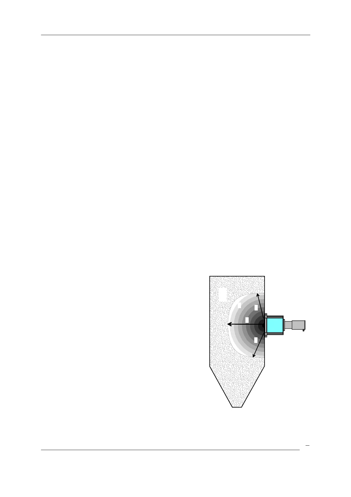
(see Figure 2).
Provided the product to be measured shows a
homogeneous structure, no measurement errors will
occur.
Figure 2: Saturation layer
S = saturation layer thickness
1 = measured material layer
1
2
S
S
S


 To Next Page