01/10 347 LB 444 K-40
29
3.2 Push <sk2> to select Product Data and <more> to call parameters sequentially.
Select product: “1”
Select current output 0 –20 or 4 – 20 mA
Define current output limit values 0/4 and 20 mA:
x% K20 = 4 mA
y% K20 = 20 mA
Define behavior of the current output in case of error message.
Define relay 2: Function (Min), switch point (e.g. 10% )
Hysteresis (e.g. 5%)
Define relay 3: Function (Max), switch point (e.g. 20% )
Hysteresis (e.g. 5%)
Periodic printout:
e.g. 10 min
Push <done> to return to menu group.
7.2.2 Calibration
Prerequisites
Device and detector have been installed.
The device must be turned on at least 1 h prior to the start of calibration.
Container or pipeline have to be filled with the product to be measured.
The calibration is performed as follows:
At different K
2
0 concentrations, the counts supplied by the detector are read into the
memory. The concentration values determined in the laboratory (analysis values) are
entered in a further storage sequence. The correlation of the memories is described
below using one calibration data set as an example.
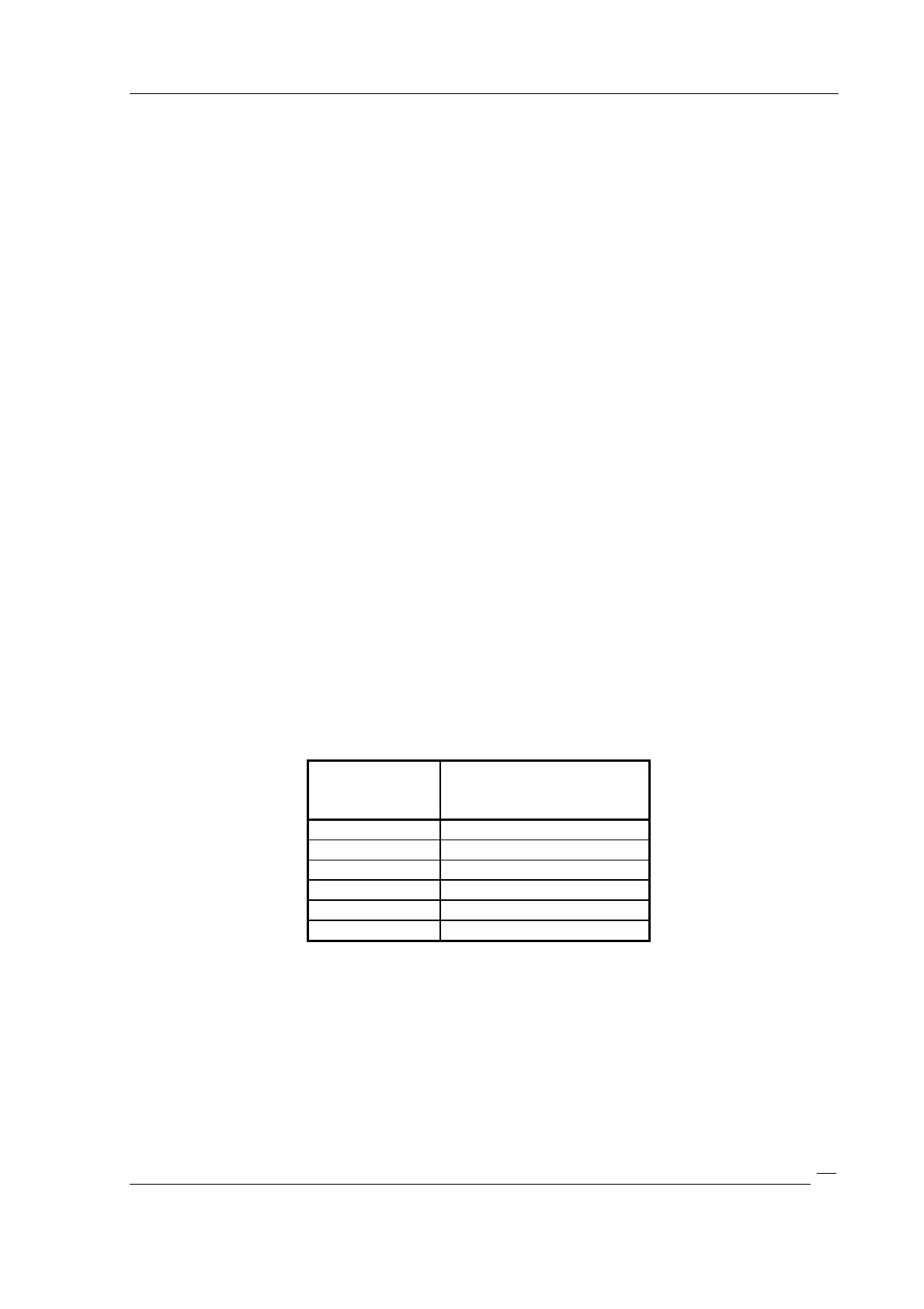
Count rates:
Concentration K20
(lab values):
1: 405 10.2
2 : 583 17.3
3 : 785 25.4
10 : 0 0
At least 2 calibration points must be available.
The calibration points should be distributed fairly equally over the entire
measurement range. However, some calibration points may lie outside the measure-
ment range. A calibration only with points outside the measurement range is not
advisable.
Its also possible to use the background radiation as a calibration point. This has to be
measured
d) with empty vessel or
 Loading...


