01/10 347 LB 444 K-40
7
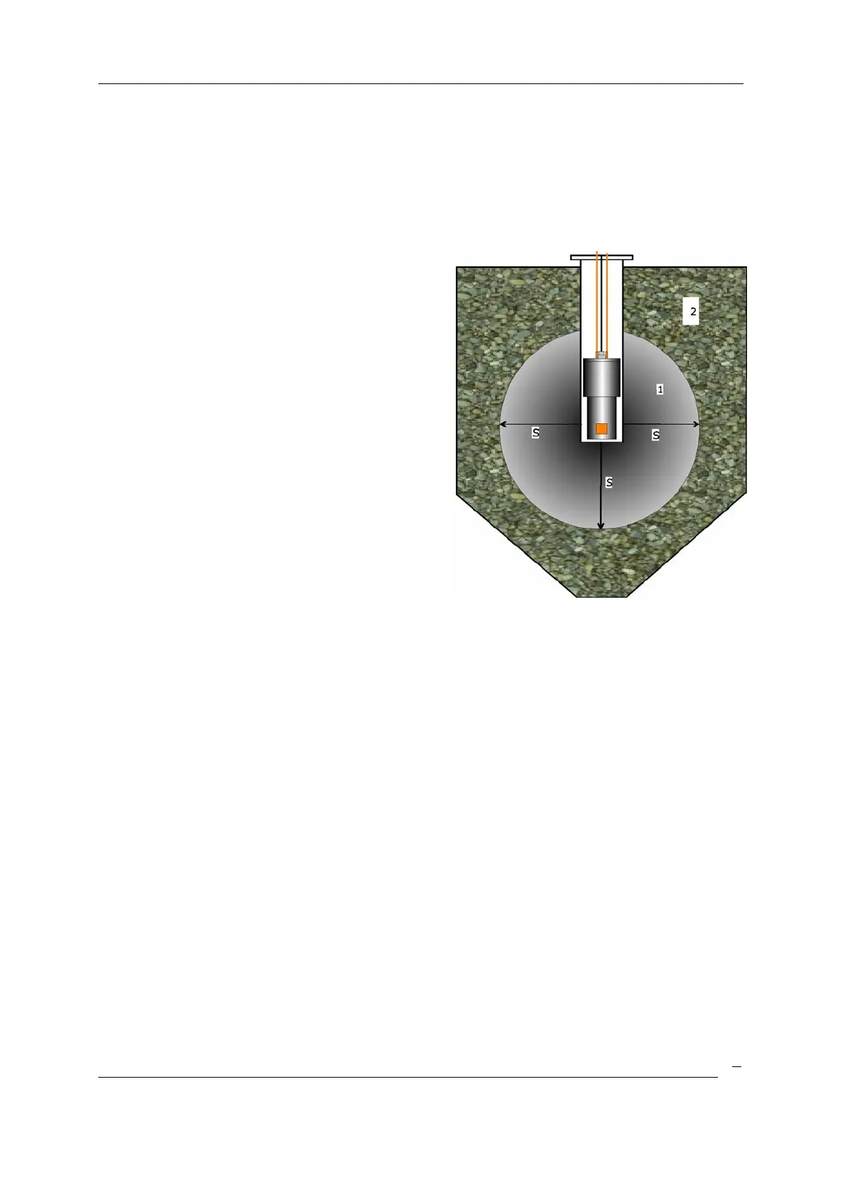
4.3 Installation of the Detector LB 5402 in a Bunker
The detector is installed into a protective pipe, front side closed, and inserted into a
bunker. The distance of the material surface in front of the detector head sensitive to
radiation (position of the scintillation crystal) should on all sides correspond to the
calculated saturation thickness.
If hot liquids are used a cooling water jacket for
the probe is necessary.
The detector temperature must never
exceed 50°C.
No crystallization must occur on the protective
pipe. If necessary, the protective pipe has to be
provided with a thermal insulation and possibly
with a heating jacket.
Crystallizations would significantly falsify the
measured results, since the potassium
concentration in the crystallized layer is
typically higher than in the liquid solution.
S = saturation layer thickness
1 = measured material layer
2 = material not covered by the measurement
Figure 4: Measurement in a container
4.4 Measurement in a Pipe
When measuring in a pipe, the saturation layer thickness is usually not achieved or at
least not achieved in all directions. In the case of large pipes, the saturation layer
thickness is usually achieved in the longitudinal direction of the pipeline, However,
transverse to the pipeline axis, the saturation layer is not always achieved. This can have
an effect on the measurement result, which is larger:
a) the smaller the pipe is
b) the stronger the density varies in the pipeline, (see Figure 6).
The measurement of the saturation thickness is also affected by the diameter of the pipe,
the pipe material and the wall thickness of the pipe.
A correction of the influence is possible in some cases by an additional density
measurement.
This will require an extended period of time for the recording of
a) Density values
b) Displayed K2O values and
c) the appropriate, K2O values determined in the laboratory.

 Loading...


