CYLINDER HEAD
5. Turn:
• Crankshaft
(several turns counterclockwise)
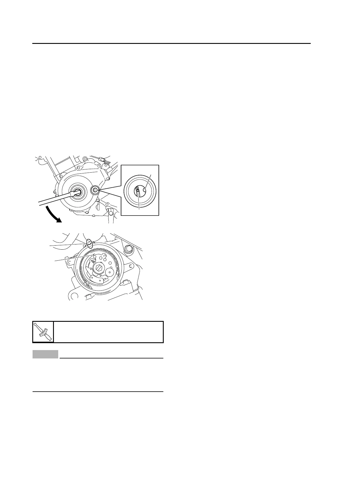
6. Check:
•“I” mark “a”
Align the “I” mark on the generator rotor with
the stationary pointer “b” on the generator
cover.
•“I” mark “c”
Align the “I” mark on the camshaft sprocket
with the stationary pointer “d” on the cylinder
head.
Out of alignment → Correct.
Refer to the installation steps above.
7. Tighten:
• Camshaft sprocket bolt
NOTICE
ECA22B1010
Be sure to tighten the camshaft sprocket bolt
to the specified torque to avoid the possibil-
ity of the bolt coming loose and damaging
the engine.
8. Measure:
9. Valve clearance
Out of specification → Adjust.
T
R
.
.
Camshaft sprocket bolt
30 Nm (3.0 m·kgf, 22 ft·lbf)
b
a
d
c



 To Next Page