EasyManua.ls Logo

Binder KBF 720 - Page 53

Default Icon
140 pages
Print Icon
To Next Page IconTo Next Page
To Previous Page IconTo Previous Page
Loading...
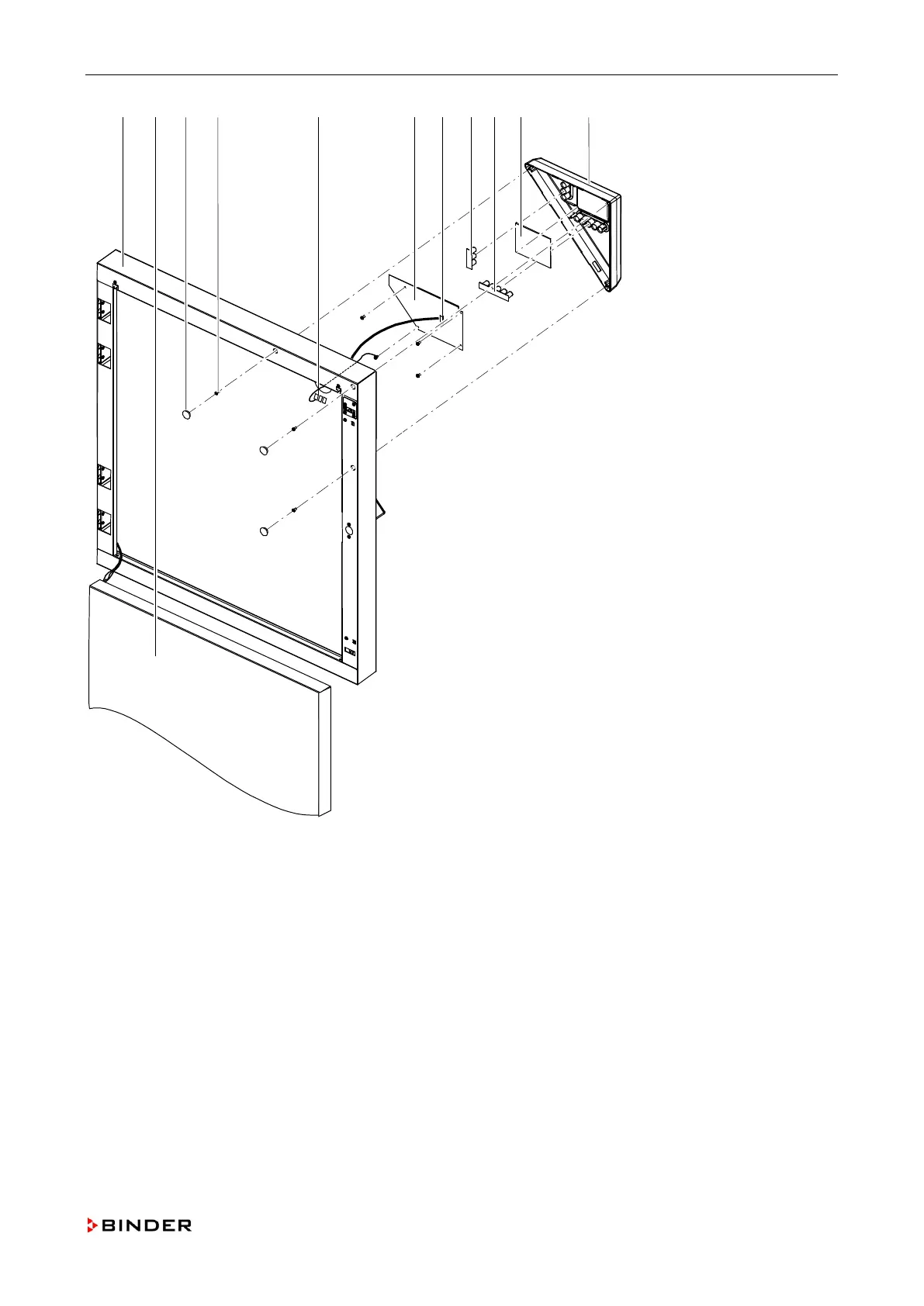
Repair work at the outer door
A C D E F G K J H I B
Figure 15: Replacing the triangle instrument box
A
Door frame
G
Plug of controller cable
B
Interior side of the outer door
H
Switch mat 3-fold
C
Covers
I
Switch mat 5-fold
D
Screws
J
Filter pane
E
Connection of the grounding cable
K
Housing of instrument box
F
Controller display
Please note that demounting the interior side of the outer door is necessary only if, while demounting the tri-
angle instrument box, the fixing screws have fallen into the door frame!
Service Manual KBF (E5.2) 04-2015 53

Table of Contents

Other manuals for Binder KBF 720

Related product manuals