EasyManua.ls Logo

Binder KBF 720 - Page 55

Default Icon
140 pages
Print Icon
To Next Page IconTo Next Page
To Previous Page IconTo Previous Page
Loading...
Repair work at the outer door
B
A
H
C
D
G
I
J
K
M
F
E
(I)
(II)
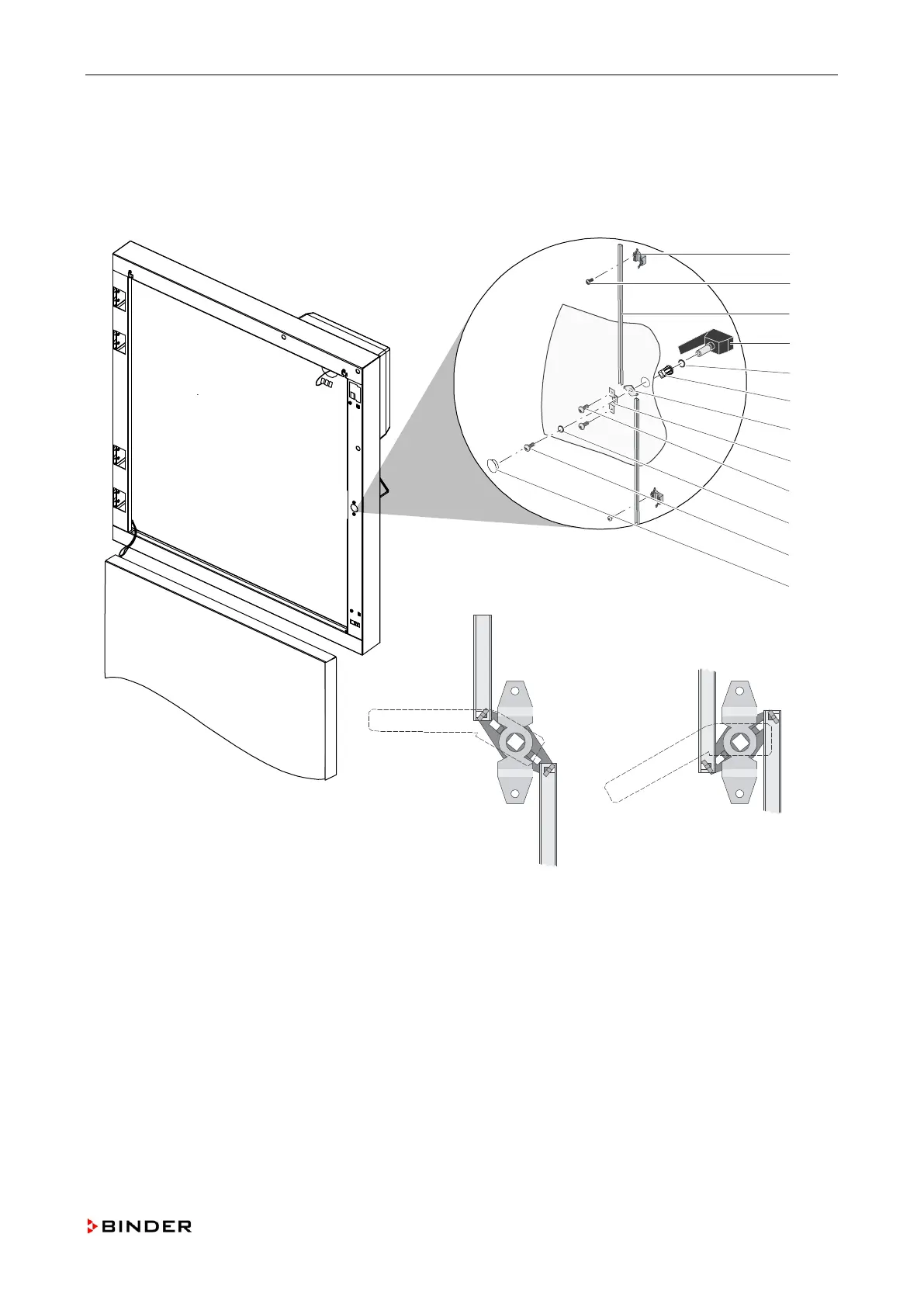
When installing the push rods, the open side of the profile must point in direction of the unit. During as-
sembling push rod lever (G) and axle bearing (H), pay attention that the guiding hooks of the push rod
lever are within the guiding nuts of the axle bearing and that the door handle (D) can be turned into door
closed position (I) and door open position (II).
Figure 16: Replacing the closing device of the outer door
A
Push rod guide
H
Axle bearing
B
Screw
I
Screws
C
Push rod
J
Washer
D
Door handle
K
Screw
E
O-ring
M
Cover
F
Axle guide
(I)
Door closed position
G
Push rod lever
(II)
Door opened position
Service Manual KBF (E5.2) 04-2015 55

Table of Contents

Other manuals for Binder KBF 720

Related product manuals