MK / MKT (E5) 03/2019 page 25/158
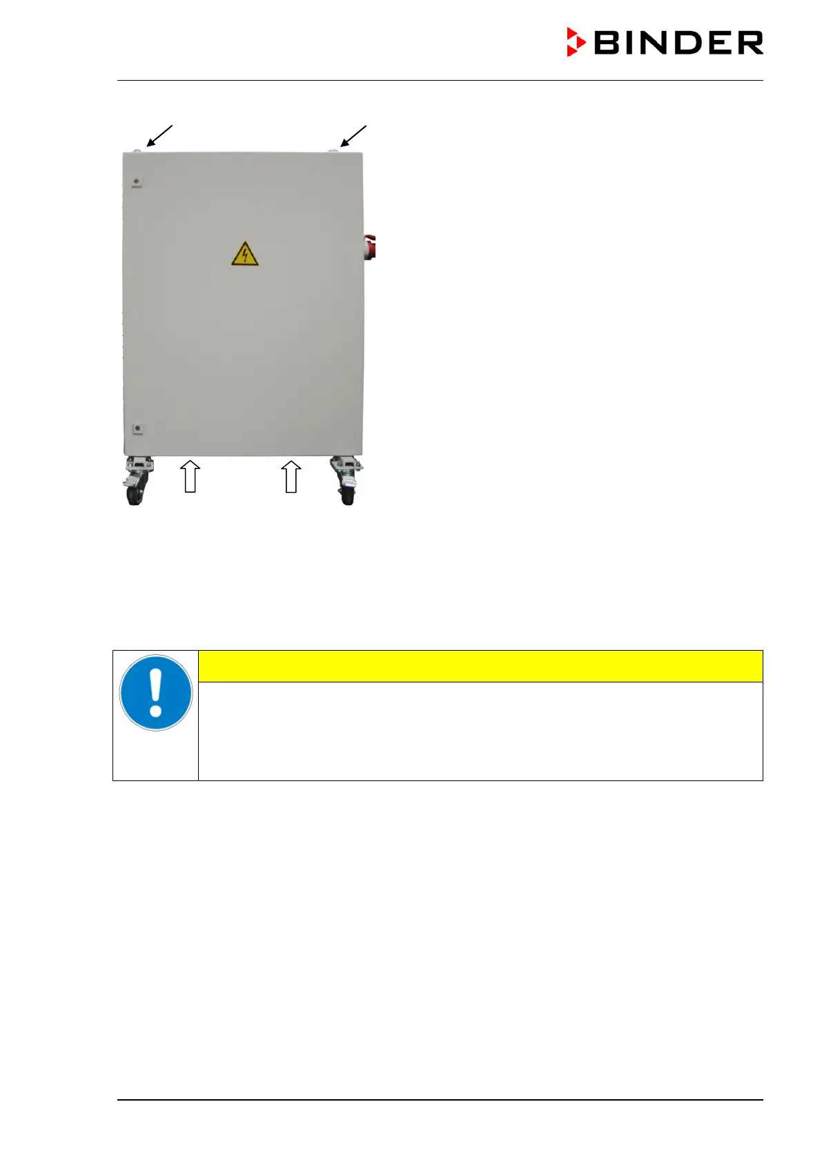
(a) Eyelets for lifting with a lifting crane or fork lifter
(b) Positions for a fork lifter
Figure 11: Positioning of aids for lifting the voltage
and frequency changer
For the installation of the voltage and frequency changer behind the chamber, provide a rear wall distance
of the chamber of approx. 1 m / 3.3 ft.
If possible, fix the voltage and frequency changer at the chamber. For this purpose, an Allen key size 4 is
required. Connect the slots at the end of the chassis with two M6 screws to the threads provided below on
the rear panel of the chamber (see Figure 12).
CAUTION
Danger of overheating.
Damage to the voltage and frequency changer.
∅ Do NOT install the voltage and frequency changer in unventilated recesses.
Ensure sufficient ventilation for dispersal of the heat.
The voltage and frequency changer is equipped with four castors. The rear castors can be easily locked
via the attached brakes