Chapter 5 Programmable Parameters
Evia HF / HF-T Technical Manual
PAGE 48
Termination
Evia CRT-P extends PVARP (Post Ventricular Atrial Refractory Period) to the VA interval + 50 ms.
5.12 Adjustment of the PMT Protection Window
The PMT protection window can be automatically adjusted. This automatic adjustment functions in the
following manner:
When the PMT is detected and terminated, the PMT protection interval is extended by 50 ms. If no
additional PMTs arise within seven days, the length of the PMT protection interval is reduced by 50 ms.
The initial values of the PMT protection interval in the automatic setting at 250 ms after Vp and 400 ms
after a PVC.
5.13 Right/left Ventricular Capture Control (VCC)
5.13.1 Feature Description
The Right/Left VCC feature periodically measures the capture threshold, and automatically adjusts
the pacing output (with a programmable safety margin) independently for the Right and Left Ventricles
when programmed ON. Additionally, the feature continuously assesses ventricular pacing capture on a
beat-to-beat basis and responds to any loss of capture with a safety back-up pulse. During the clinical
evaluation of the Ventricular Capture Control algorithm, it was demonstrated that use of Ventricular
Capture Control can increase device longevity (as compared to standard programming).
Differences in the signal morphology between the polarization artifact and the evoked response signal
are used to distinguish capture events from non-capture events. The polarization artifact is the signal
caused by the pacing pulse between the pacing electrode and the cardiac tissue. The evoked response
signal is the intracardiac signal measured during electrical activation of the myocardium.
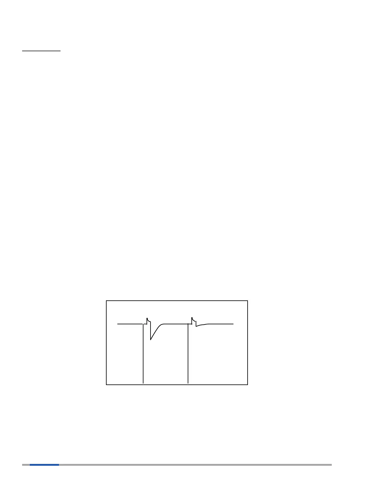
Figure 31 shows an example of an evoked response signal and a polarization artifact. After an effective
blanking period of 20 ms, the signal is evaluated over the next 60 ms. Several characteristics of the
signal falling into this window are evaluated in order to discriminate the evoked response (capture) from
polarization artifact (possible non-capture).
Figure 31: Example of a Capture and a Non-Capture Beat
Table 13 contains a list and description of the acronyms and terms pertaining to the VCC feature used
in this manual.