18.8 Traverse function
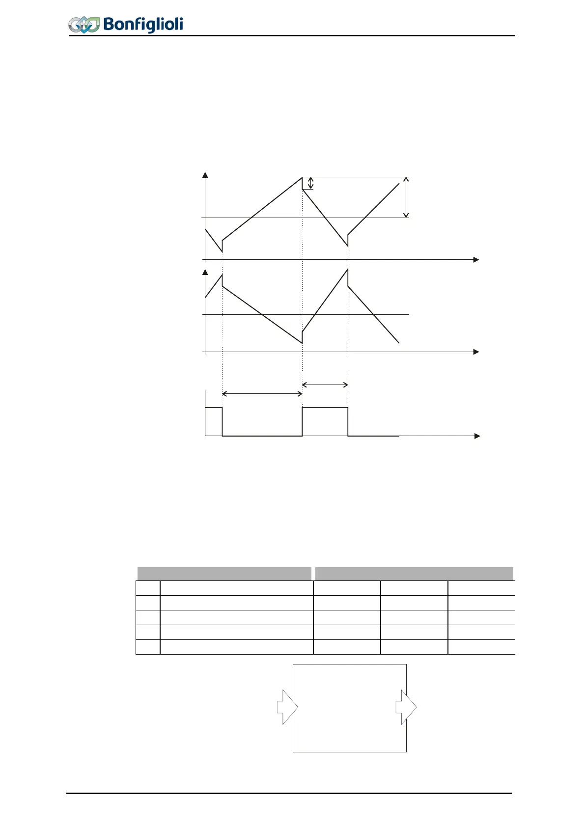
With the traverse function, a triangle-shaped frequency signal with the acceleration
and deceleration times to be set is superimposed on the output frequency. The re-
sulting signal courses of the reference frequency of mas
ter drive and slave drive are
shown in the following diagrams. The function can be used, for example, for drives
which wind up thread on coils in textile machines. To avoid winding errors at the
turning point of the thread guide, a proportional jump is per
formed which causes a
quick speed change.
In the case of the master drive, the superimposed traverse frequency proceeds line-
arly to the limit Traverse Amplitude 438
and then reverses its direction. When the
direction is reversed, a proportional step is affected. Via a handshake sig
master drive informs the slave drive that the traverse output has changed its direc-
tion. The traverse function of the slave drive has the same gradient as the trav
erse
function of the master drive, but with opposite sign. When the slave drive reaches
the limit Traverse Amplitude 438 before switch-over of the handshake sig
frequency is maintained until switch-over is affected. If the handshake signal is re-
ceived before the frequency limit is reached, the direction is reversed immediately.
436 Acceleration Time 0.01 s 320.00 s 5 s
437 Deceleration Time 0.01 s 320.00 s 5 s
438 Traverse Amplitude 0.01 % 50.00 % 10 %
439 Proportional Step 0.01 % 50.00 % 0.01%
Signal “14 – Traverse Output” is added to the reference frequency value.
Acceleration
Time
436
Deceleration
Time
437
Proportional Step 439
Traverse Amplitude 438
Master drive
Reference
Frequency
48
Reference
Frequency
48
f
t
t
t
f
0
0
Slave drive
Handshake
Operation Mode
435
Acceleration Time
436
Deceleration Time
437
Traverse Amplitude
438
Proportional Step
439
Traverse function
Input signals Output signals
Reference Frequency
48
Handshake Traverse Function
49
14 - Sweep Output
15 - Sweep Handshake
(from Master drive)
254 Operating Instructions ACU 06/13

 Loading...