The synchronization of the rotor time constant as a function of the winding tempera-
ture can be adjusted. The default values should normally be sufficient
that neither an adjustment of the rotor time constants via the parameter Rat
correction factor 718 nor an adjustment of the temperature synchroniza
parameter Temperature coefficient 466 is necessary. If an adjustment is n
please remember that the rotor time constant is calculated by the guided commis-
sioning via the machine data. The
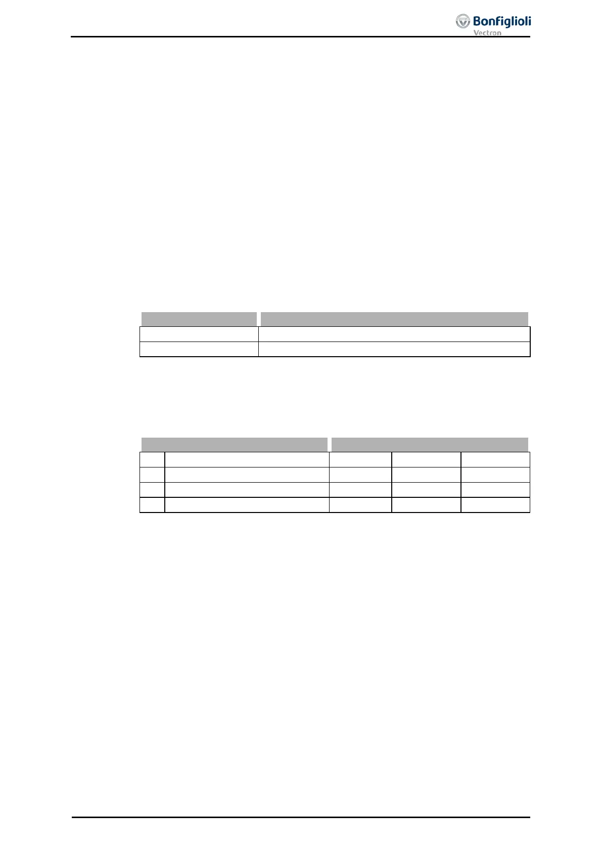
Adjusting temperature 467
temperature at which the optimiza
tion of the extended machine data was carried out.
The temperature can be read out via the actual value parameter Winding tempera-
226 and can be used in the optimization for the parameter.
18.7.3 Speed Sensor Monitoring
Failures of the speed sensor lead to a faulty behavior of the drive, as the measured
speed forms the foundation of the control system. By default, the speed sensor moni-
toring system continuously monitors the speed sensor signal, the track signals. If an
expansion module EM is connected, the number of division marks is monitored addi-
tionally. If, while the frequency inverter is released, a faulty signal is recognized for
longer than the timeout, a fault switch-off is affected. If the parameter Operation
mode 760 is set to zero, the monitoring function is deactivated.
The function is deactivated
A fault message is displayed according to the timeouts set.
The speed sensor monitoring is to be parameterized in the part functions according
to the application. The monitoring function becomes active with the release of the
fre
quency inverter and the start command. The timeout defines a monitoring time in
which the condition for the fault switch-off must be ful
filled without interruption. If
one of the timeouts is set to zero, this monitoring function is deactivated.
763 Timeout: Direction of rotation fault 0 ms 65000 ms 1000 ms
The actual speed measured is compared with the output value of the speed control-
ler. If the actual speed value is exactly zero for the time selected with the parameter
Timeout: Signal fault 761, although a reference value is available, the fault is dis-
played with the message "F1430".
Timeout: Track fault
The actual speed measurement monitors the sequence in time of the signals in the
quadruple evaluation of the speed sensor operation mode. If the speed sensor signal
is faulty for the time selected with the parameter Timeout: Channel fault 762,
the
fault is displayed with the message "F1431".
Timeout: Direction of rotation fault
The actual speed measured is compared with the reference speed. If the sign be-
tween reference value and actual value differs for the time selected with the parame-
ter
Timeout: Direction fault 763, the fault is displayed with the message "F1432
The monitoring function is reset when the drive mechanism has moved in the refer-
ence value direction by a quarter of a revolution.
06/13 Operating Instructions ACU 253

 Loading...