15.4.8 Fixed Value Change-Over
As a function of the selected configuration, the reference figures are specified via the
assignment of the Reference frequency source 475 or
source 476. Accordingly, there can be a change between the fixed values by connec-
tion of the logic signals with the parameters
Fixed frequency change-over 1 66
Fixed frequency change-over 2 67 or the parameters Fixed percent change-over 1
75, Fixed percent change-over 2 76.
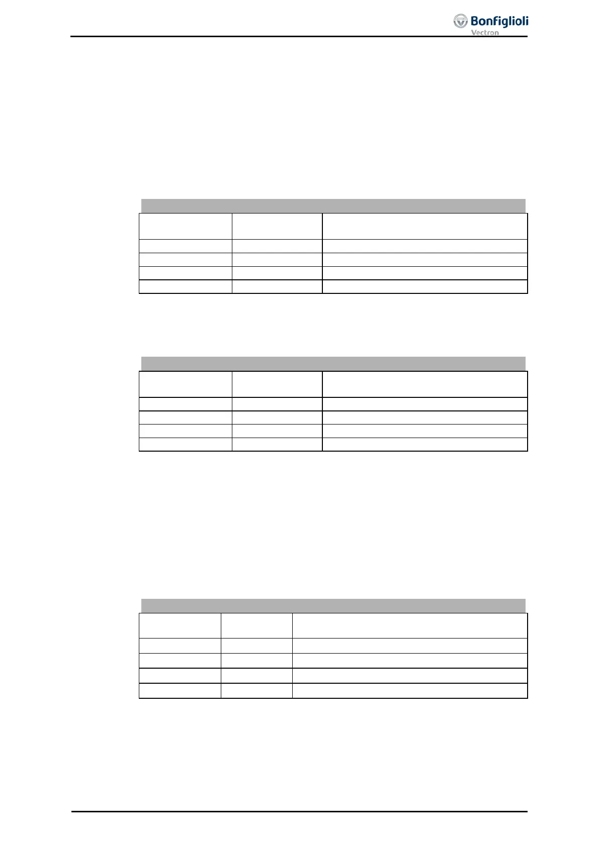
By combining the logic states of the fixed frequency change-over modes 1 and 2,
fixed frequencies 1 through 4 can be selected:
Fixed frequency
change-over 1 66
Fixed frequency
change-over 2 67
Function / active fixed value
0 = contact open 1 = contact closed
By combining the logic states of the fixed percentage change-over modes 1 and 2,
fixed frequencies 1 through 4 can be selected:
Fixed percentage
change-over 1
75
Fixed percentage
change-over 2
76
Function / active fixed value
0 = contact open 1 = contact closed
15.4.9 Motor Potentiometer
The parameters Reference frequency source 475, and Reference percentage
source 476 contain operation modes with motor potentiometer. The
mode 474 defines the behavior of the motor potentiometer function and the parame-
ters
Frequency Motorpoti Up 62, Frequency Motorpoti Down 63 or Percent Motor-
poti Up
72, Percent Motorpoti Down 73 the connection with the available logic sig-
Motor Potentiometer Control
Motorpoti Up
Function
0 0 Output signal does not change.
1 0 Output value rises at set ramp.
0 1 Output value drops at set ramp.
1 1 Output value is reset to initial value.
0 = contact open 1 = contact closed
06/13 Operating Instructions ACU 199

 Loading...