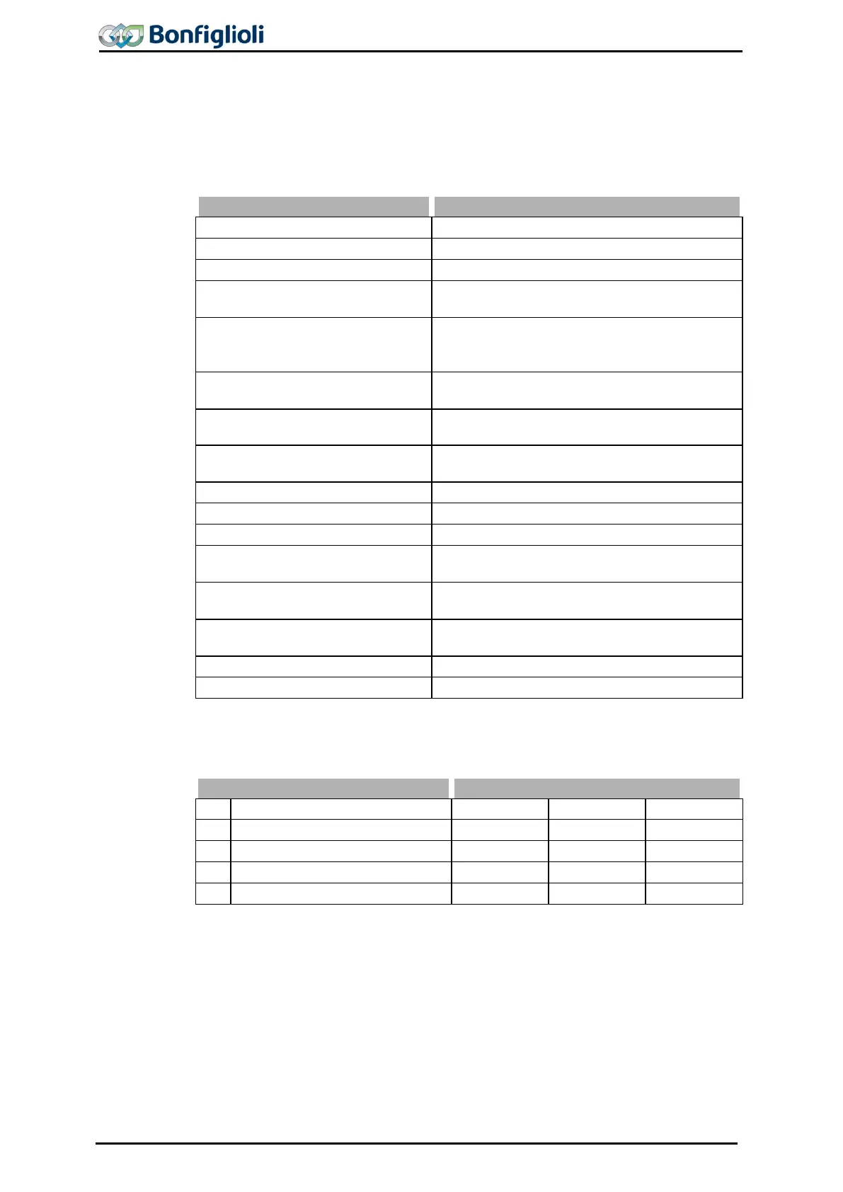
15.5.2 Comparator
With the help of software functions Comparator 1 and 2, various comparisons of ac-
tual values with percentage-adjustable fixed values can be done.
The actual values to be compared can be selected from the following table with the
parameters Op. Mode Comparator 1 540 and Op. Mode Comparator 2 543.
If an expansion module is connected, further operation modes are available.
0 - Off Comparator is switched off.
1 - Absolute current
>
.
2 - Abs. Active Current
>
.
3 - Abs. Stator Frequency
Stator frequency 210 > Maximum frequen-
cy 419.
4 - Abs. Actual Speed 1
Speed Sensor 2 Speed 220 > maximum speed
(calculated from Maximum Frequency 419 and
5 - Abs. Actual Repetition Freq.
Repetition frequency input 252 >Maximum
frequency 419.
6 -
Temp. Follow-Up.
Winding temperature 226 > tempera-
ture 100 °C
7 - Abs. Actual Frequency
Actual frequency 241 > Maximum frequen-
cy
419.
9 - DC –Link Voltage
222 > Direct voltage 1000 V.
216 >
371.
Abs Filtered Active Current
214 >
371.
12 - Abs. Internal Ref. Frequency
Internal Reference Frequency 228 >Maximum
Frequency
419.
13 - Abs. Ref. Percentage Value
Reference Percentage Value 229 > Maximum
Reference Percentage
519.
14 -
Abs. Actual Percentage Val-
ue
Actual Percentage Value 230 > Maximum
Reference Percentage
519.
15 - Abs. Analog Input MFI1A
251 > input signal 100 %
Operation modes with signs (+/-).
The switch-on and switch-off thresholds for compactors 1 and 2 are set by the para-
meters Comparator on above 541, 544 and Comparator off below 542, 545.
The percentage limits of the corresponding reference values are indicated.
204 Operating Instructions ACU 06/13

 Loading...