10.4 Speed Sensor 1
The frequency inverters are to be adapted to the application depending on the re-
quirements. A part of the available Configuration 30 demand continuous measure-
ment of the actual speed for the control functions and methods. The necessary con-
nection of an in
cremental speed sensor is done on the digital control terminals S5IND
(track A) and S4IND (track B) of the frequency inverter.
With expansion modules EM and sensor input modules, it is also possible to connect
and evaluate sensors as speed sensor 2. Please refer to the corresponding operating
instructions. Speed sensor 1 and speed sensor 2 are configured independently from
one another.
10.4.1 Operation Mode Speed Sensor 1
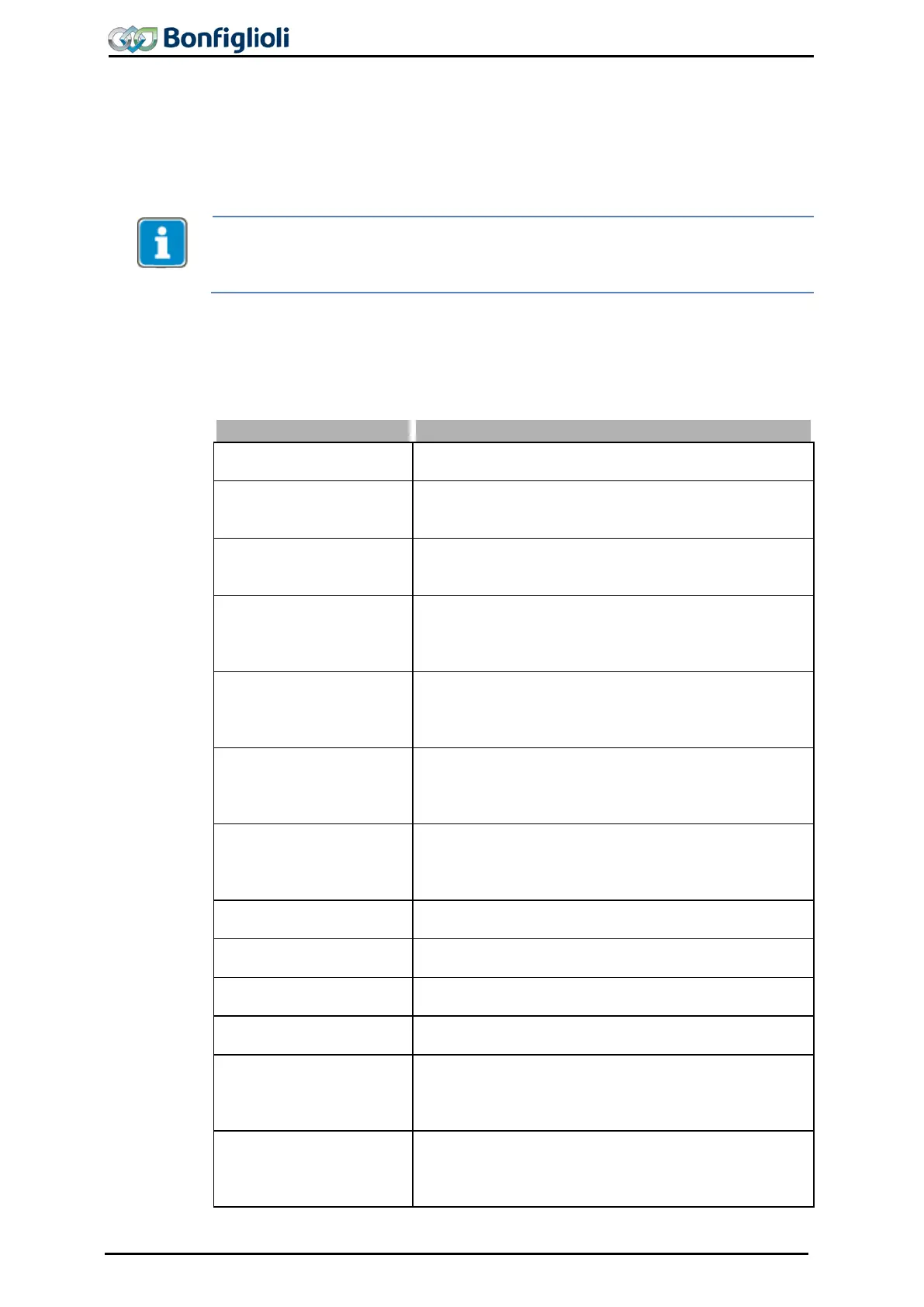
Operation mode 490 for speed sensor 1 can be selected according to the connected
incremental speed sensor. Connect an unipolar speed sensor to the stand
0 - Off
Speed measurement is not active; the digital inputs are
available for other functions.
1 – Single evaluation
Two-channel speed sensor with recognition of direction
of rotation via track signals A and B; one signal edge is
evaluated per division mark.
4 –
Quadruple evalua-
tion
Two-channel speed sensor with recognition of direction
of rotation via track signals A and B; four signal edges
are evaluated per division mark.
11 –
Single evaluation
without sign
One-channel speed sensor via track signal A; the actual
speed value is positive. One signal edge is evaluated per
division mark. The digital input S4IND is available for
12 –
Double evaluation
without sign
One-channel speed sensor via track signal A; the actual
speed value is positive. Two signal edges are evaluated
per division mark. The digital input S4IND is available
31 –
Single evaluation,
sense of rot. via
contact
One-channel speed sensor via track signal A. The actual
speed value is positive for signal “Low” and negative for
signal “High” at digital input S4IND. One signal edge is
evaluated per division mark.
32 –
sense of rot. via
contact
One-channel speed sensor via track signal A. The actual
speed value is positive for signal “Low” and negative for
signal “High” at digital input S4IND. Two signal edges
are evaluated per division mark.
101 –
Single evaluation
inverted
Same as in operation mode 1. The actual speed value is
inverted. (Alternative to exchanging the track signals)
104 –
Quadruple evalua-
tion inverted
Same as in operation mode 4. The actual speed value is
inverted. (Alternative to exchanging the track signals)
111 –
Single evaluation
negative
Same as operation mode 11. The actual speed value is
negative.
112 –
Double evaluation
negative
Same as operation mode 12. The actual speed value is
negative.
131 –
Single evaluation,
sense of rot. via
contact inverted
One-channel speed sensor via track signal A. The actual
speed value is negative for signal “Low” and positive for
signal “High” at digital input S4IND. One signal edge is
evaluated per division mark.
132 –
sense of rot. via
contact inverted
One-channel speed sensor via track signal A. The actual
speed value is negative for signal “Low” and positive for
signal “High” at digital input S4IND. Two signal edges
are evaluated per division mark.
128 Operating Instructions ACU 06/13

 Loading...