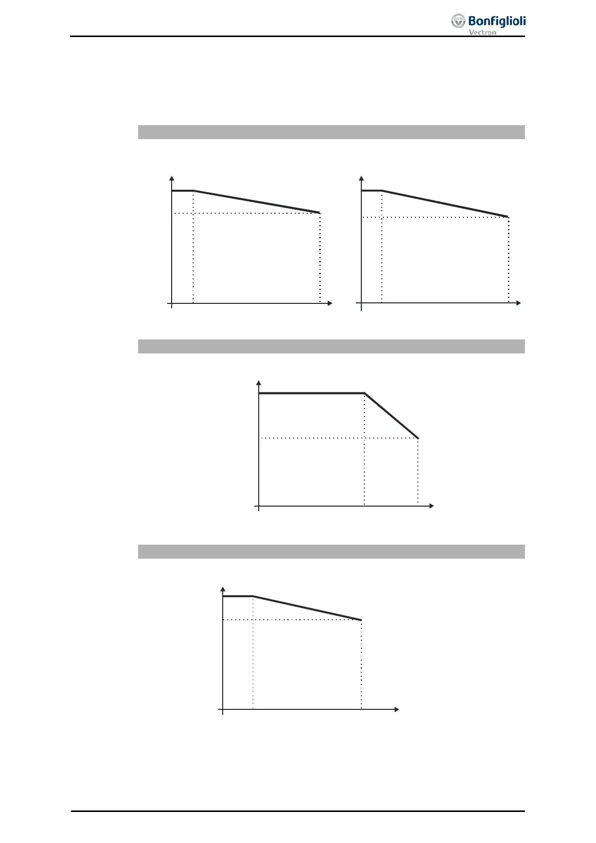
4.12 Operation diagrams
The technical data of the frequency inverters refer to the nominal point which was
selected to enable a wide range of applications. A functionally and efficient dimension-
ing (derating) of the frequency inverters is possible based on the following diagrams.
100
85
60
40
20
55
45
3000
1000
2000 4000
3000
1000
2000
4000
Power reduction (Derating),
5%/1000 m above sea level,
h = 4000 m
max
max. coolant temperature,
3.3 °C/1000 m above sea level,
Mounting altitude in m above sea level Mounting altitude in m above sea level
Output current in %
Coolant temperature in °C
100
80
63
40
20
0 10
20
30
40 50 55
Power reduction (Derating)
2.5%/K upper 40 °C, T = 55 °C
max
Output current in %
Coolant temperature in °C
100
83
63
40
20
0 400
420
440
460
480
Out
put
cur
ren
t in
%
Mains voltage equal output voltage in V
Reduction of output current at constant output power (Derating)
0.22%/ V upper 400 V, U = 480 V
max
06/13 Operating Instructions ACU 41

 Loading...