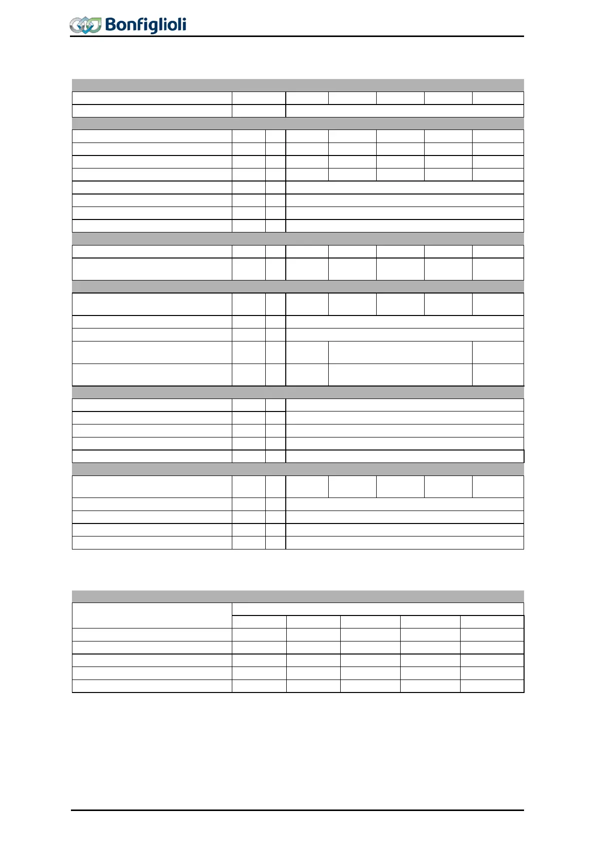
4.3 ACU 201 (0.25 to 1.1 kW, 230 V)
Recommended motor shaft power
Long-term overload current (60 s)
Short-time overload current (1 s)
Maximum input voltage, three-phase
Short circuit / earth fault proof
0 ... 1000, depending on switching frequency
Switching frequency
f kHz
2, 4, 8, 12, 16
Recommended brake resistor
(U
dBC
= 385 V)
R Ω 430 300 230 160 115
Mains current
3)
3ph/PE
1ph/N/PE; 2ph/PE
I A
2)
I A
UL type 250 VAC RK5, 3ph
1ph/N; 2ph
I A
Energy dissipation (2 kHz switching
frequency)
P W 32 38 43 53 73
0 ... 40 (3K3 DIN IEC 721-3-3)
15 ... 85; not condensing
If required by the customer, the switching frequency may be increased if the output current is reduced at the
same time. Comply with the applicable standards and regulations for this operating point.
Frequency inverter nominal power
2 kHz
4 kHz
8 kHz
12 kHz
16 kHz
1)
Three-phase connection requires a commutating choke.
2)
One- and two-phase connection requires a commutating choke.
3)
Mains current with relative mains impedance ≥ 1% (see chapter ”Electrical installation“)
4)
Maximum output current = 9.5 A with single-phase and two-phase connection
5)
Reduction of switching frequency in thermal limit range
6)
Maximum current in continuous operation
7)
The device for single phase connection is not listed in the product catalogue and only available on request.
32 Operating Instructions ACU
06/13

 Loading...