EasyManua.ls Logo

BONFIGLIOLI ACTIVE Cube ACU 201-01 User Manual

BONFIGLIOLI ACTIVE Cube ACU 201-01
292 pages
To Next Page IconTo Next Page
To Previous Page IconTo Previous Page
Page #262 background image
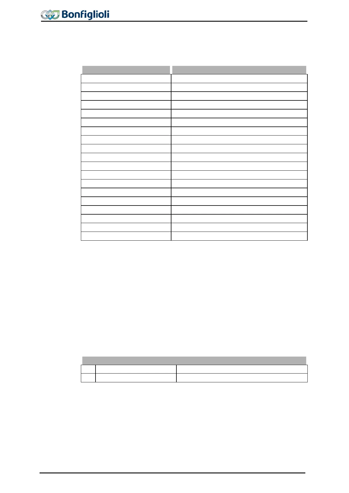
The Reset memory 237 parameter to be selected in the PARA menu branch of the
operating unit enables purposeful resetting o
f the individual mean and peak values.
The peak value and the mean value with the values stored in the period are over-
written with the parameter value zero.
Reset memory 237
Function
0 -
No Reset
Values of actual value memory remain unchanged.
1 -
Peak Value Long Term Ixt
Reset Peak value long-term Ixt 231.
2 -
Peak Value Short Term Ixt
Reset Peak value short-term Ixt 232.
3 -
Peak Value Vdc
Reset
Peak value Vdc
287.
4 -
Average Value Vdc
Delete
Average value Vdc.
288
.
5 -
Peak Value Tc
Reset
Peak value Vdc
289.
6 -
Average Value Tc
Delete
Average value Vdc.
290.
7 -
Peak Value Ti
Reset
Peak value Ti
291.
8 -
Average Value Ti
Delete
Average value Ti.
292.
9 -
Peak Value Iabs.
Reset
Peak value Iabs. 293
.
10 -
Average Value Iabs
Delete
Average Iabs 294
.
11 -
Peak Value Pactive pos.
Reset
Peak value active power pos. 295
.
12 -
Peak Value Pactive neg.
Reset
Peak value active power neg. 296
.
13 -
Average Value Pactive
Delete
Average value active power
297
.
16 -
Energy, positive
Reset parameter
Energy positive
301
.
17 -
Energy, negative
Reset parameter Energy negative 302.
100 -
All Peak Values Reset all peak values stored.
101 -
All Average Values
Delete average values and stored values.
102 -
All Values
Delete the entire actual value memory.
19.4 Actual Values of the System
The calculation of the actual figures of the system is based on the parameterized
system data. Specific to the application, the parameters are calculated from the fac-
tors, electrical variables and the controls. The correct display of the actual figures is a
function of the data of the system to be parameterized.
19.4.1 Actual System Value
The drive can be monitored via the actual value Actual System Value 242.
The Actual frequency 241 to be monitored is multiplied by the
Actual system value
factor 389 and can be read out via the parameter Actual system value 242, i.e. Ac-
tual frequency 241 x Actual system value factor 389 = Actual system value 242.
Actual System Value
No.
Description
Function
242
Actual System Value
Calculated frequency of drive.
262 Operating Instructions ACU 06/13

Table of Contents

Question and Answer IconNeed help?

Do you have a question about the BONFIGLIOLI ACTIVE Cube ACU 201-01 and is the answer not in the manual?

BONFIGLIOLI ACTIVE Cube ACU 201-01 Specifications

General IconGeneral
Rated Power0.75 kW
Protection ClassIP20
Input Voltage200-240 VAC
Switching Frequency4 kHz
CommunicationModbus RTU
Operating Temperature-10°C to +50°C

Summary

General information about the documentation

Instruction manuals

Details on the different types of manuals available for the frequency inverter, including Quick Start Guide, Operating Instructions, and Application Manual.

This document

Description of the present documentation, its scope, and importance of reading the user manual carefully for safe operation and increased reliability.

Warranty and liability

Information on the manufacturer's obligations, warranty stipulations, and exclusions of liability for damages due to misuse or non-compliance.

Obligation

User manual must be read and complied with by all personnel involved in transport, assembly, installation, and operation of the frequency inverter.

Copyright

Details the copyright ownership of the manual and restrictions on disclosure, copying, and exploitation of its contents.

Storage

Instructions on storing the documentation as an integral part of the frequency inverter and handing it over when sold to other users.

General safety instructions and information on use

Terminology

Defines groups of persons with required qualifications: Operator, Operating Staff, Qualified Staff, Qualified Electrician, Instructed Person, and Expert.

Designated use

Specifies that the frequency inverter is designed for industrial plants/machines and must comply with relevant directives and standards.

Misuse

Defines misuse as any use other than designated use, including operation by uninstructed staff or without safety equipment.

Residual risks

Identifies residual hazards like electrical, electrostatic charging, thermal hazards, charged capacitors, and equipment falling hazards.

Safety and warning signs at frequency inverter

Instructions to comply with safety information on the inverter and not remove warning signs.

Warning information and symbols used in the user manual

Explains hazard classes (DANGER, WARNING, CAUTION, NOTE) and symbols for general hazard, electrical voltage, and prohibition.

Directives and guidelines to be adhered to by the operator

Operator directives include ensuring access to regulations, authorized person verification, and compliance with country-specific laws.

Operator's general plant documentation

Operator should issue internal operating instructions and include the inverter's user manual in the plant's overall documentation.

Operator's/operating staff's responsibilities

Responsibilities include selecting qualified staff, ensuring general work safety, proper tool usage, and avoiding modifications.

Organizational measures

Measures include staff training, proper use of components, compliance with third-party product documentation, and transport/storage guidelines.

Safety Instructions on Function „Safe Torque Off“ (STO)

Safety instructions for STO function, emphasizing proper installation and commissioning by qualified staff.

Scope of Supply

ACU 201 (up to 3.0 kW) and 401 (up to 4.0 kW)

Details the scope of supply for ACU 201 and 401 frequency inverters up to 3.0 kW and 4.0 kW respectively.

ACU 201 (4.0 to 9.2 kW) and 401 (5.5 to 15.0 kW)

Details the scope of supply for ACU 201 and 401 frequency inverters ranging from 4.0 to 9.2 kW and 5.5 to 15.0 kW.

ACU 401 (18.5 to 30.0 kW)

Details the scope of supply for ACU 401 frequency inverters with power ratings from 18.5 to 30.0 kW.

ACU 401 (37.0 to 65.0 kW)

Details the scope of supply for ACU 401 frequency inverters with power ratings from 37.0 to 65.0 kW.

ACU 401 (75.0 to 132.0 kW)

Details the scope of supply for ACU 401 frequency inverters with power ratings from 75.0 to 132.0 kW.

Technical Data

General technical data

Provides general technical data including CE conformity, EMC directive, interference immunity, UL approval, safety function, ambient temperature, and environmental class.

Technical Data – Control Electronic Equipment

Details technical data for control terminals X210A and X210B, including digital inputs/outputs and wiring specifications.

ACU 201 (0.25 to 1.1 kW, 230 V)

Presents detailed technical specifications for ACU 201 frequency inverters from 0.25 to 1.1 kW at 230 V.

ACU 201 (1.5 to 3.0 kW, 230 V)

Presents detailed technical specifications for ACU 201 frequency inverters from 1.5 to 3.0 kW at 230 V.

ACU 201 (4.0 to 9.2 kW, 230 V)

Presents detailed technical specifications for ACU 201 frequency inverters from 4.0 to 9.2 kW at 230 V.

ACU 401 (0.25 to 1.5 kW, 400 V)

Presents detailed technical specifications for ACU 401 frequency inverters from 0.25 to 1.5 kW at 400 V.

ACU 401 (1.85 to 4.0 kW, 400 V)

Presents detailed technical specifications for ACU 401 frequency inverters from 1.85 to 4.0 kW at 400 V.

ACU 401 (5.5 to 15.0 kW, 400 V)

Presents detailed technical specifications for ACU 401 frequency inverters from 5.5 to 15.0 kW at 400 V.

ACU 401 (18.5 to 30.0 kW, 400 V)

Presents detailed technical specifications for ACU 401 frequency inverters from 18.5 to 30.0 kW at 400 V.

ACU 401 (37.0 to 65.0 kW, 400 V)

Presents detailed technical specifications for ACU 401 frequency inverters from 37.0 to 65.0 kW at 400 V.

ACU 401 (75.0 to 132.0 kW, 400 V)

Presents detailed technical specifications for ACU 401 frequency inverters from 75.0 to 132.0 kW at 400 V.

Operation diagrams

Provides diagrams illustrating derating due to installation height, coolant temperature, and mains voltage.

Mechanical Installation

ACU 201 (up to 3.0 kW) and 401 (up to 4.0 kW)

Details the standard mounting dimensions and installation possibilities for ACU 201 and 401 inverters up to 3.0 kW and 4.0 kW.

ACU 201 (4.0 to 9.2 kW) and 401 (5.5 to 15.0 kW)

Details the standard mounting dimensions and installation possibilities for ACU 201 and 401 inverters from 4.0-9.2 kW and 5.5-15.0 kW.

ACU 401 (18.5 to 30.0 kW)

Details the standard mounting dimensions and installation possibilities for ACU 401 inverters from 18.5 to 30.0 kW.

ACU 401 (37.0 to 65.0 kW)

Details the standard mounting dimensions and installation possibilities for ACU 401 inverters from 37.0 to 65.0 kW.

ACU 401 (75.0 to 132.0 kW)

Details the standard mounting dimensions and installation possibilities for ACU 401 inverters from 75.0 to 132.0 kW.

Electrical Installation

EMC Information

Provides measures for compliance with EMC requirements, including installation on metal panels, equipotential bonding, and cable management.

Block diagram

Presents a block diagram illustrating the connections and functions of control terminals X210A, X210B, and X10.

Optional Components

Details optional hardware modules like Control Unit KP500, Communication modules (CM), and Expansion modules (EM).

Connection of Unit

Provides guidelines for dimensioning conductor cross-sections and typical cross-sections for mains and motor connections.

Mains Connection

Instructions for mains connection, emphasizing safety, cable selection, and separation from other lines.

Motor Connection

Guidelines for motor connection, recommending shielded cables and proper grounding.

Connection of types

Illustrates mains and motor connection diagrams for various ACU 201 and 401 models.

Control Terminals

Describes the control terminals, their wiring, and configuration options for reliable and economical operation.

Configurations overview

Presents a table summarizing possible combinations of functions and control methods available in different configurations.

Installation notes according to UL508c

Provides specific installation notes for UL508c compliance, including fuse types, temperature limits, and conductor specifications.

Control Unit KP500

Menu Structure

Illustrates the menu structure of the control unit, detailing navigation using arrow keys, ESC, and ENT.

Main Menu

Describes the main menu branches (VAL, PARA, CPY, CTRL) for displaying parameters and functions.

Actual Value Menu (VAL)

Explains how to display and select actual values, switch data sets, and monitor parameters during commissioning.

Parameter Menu (PARA)

Details how to navigate, select, and edit parameters, including setting factory defaults and managing data sets.

Copy Menu (CPY)

Explains the copy function for uploading/downloading parameter values between the control unit and the frequency inverter.

Reading Data from Control Unit

Describes how to configure and activate parameter transmission from the control unit to the frequency inverter.

Control Menu (CTRL)

Explains how to access the CTRL menu for controlling the drive and mentions the requirement of digital inputs for output enabling.

Controlling the Motor via the Control Unit

Details how the control unit enables motor control based on selected operation modes and parameter settings.

Commissioning of the Frequency Inverter

Switching on Mains Voltage

Safety checks before switching on mains voltage, including connection verification and discharge status.

Setup Using the Control Unit

Guides through the guided commissioning process for parameter settings, including configuration selection and parameter identification.

Check direction of rotation

Procedure to check the drive's direction of rotation against the reference value and how to correct it by exchanging motor phases.

Speed sensor

Explains the selection of actual speed value source and parameter settings for speed sensors, including division marks and operation modes.

Inverter Data

Serial Number

Information on the serial number, device type, fabrication data, and nameplate details.

Optional Modules

Details on modular hardware extension via plug-in slots and their designations.

Inverter Software Version

Indicates where to find the firmware version and software key on the inverter.

Set Password

Explains how to set a password for protection against unauthorized access to parameter changes.

Control Level

Defines the control level 28, which determines the scope of parameterizable functions, particularly for qualified users.

User Name

Describes how to enter a user name via the optional control software VPlus for plant or machine designation.

Configuration

Explains Configuration 30 for assigning control inputs/outputs and software functions, offering various control options.

Machine Data

Rated Motor Parameters

Instructions for setting rated motor parameters from the rating plate or data sheet for control functions and methods.

Further motor parameters

Details additional motor data required for precise machine model calculation, including stator resistance and leakage coefficient.

Internal values

Lists parameters used for internal calculation of motor data that do not require user set-up.

Speed Sensor 1

Explains connection and configuration of Speed Sensor 1, including operation modes and division marks.

Sensor evaluation

Describes sensor evaluation accuracy levels like single, double, and quadruple evaluation for TTL and HTL sensors.

System Data

Actual System Value

Explains the use of Actual system value factor 389 for monitoring drive via Actual System Value 242.

Volume Flow and Pressure

Details parameterization factors for Nominal Volumetric Flow and Pressure, used for monitoring drive via electrical control parameters.

Operational Behavior

Starting Behavior

Describes parameterization of 3-phase machine starting behavior, including flux formation and IxR compensation.

Stopping Behavior

Defines stopping behavior via Operation mode 630, covering free stopping, holding, DC brakes, and emergency stop.

Direct current brake

Explains the direct current brake function for stopping behaviors 3, 6, 7 and search run, including braking current and time settings.

Auto Start

Describes the Auto Start function for applications permitting start at mains voltage, accelerating the drive upon supply restoration.

Search Run

Explains the search run function for synchronizing to a rotating drive, determining flux direction, and improving starting behavior.

Positioning

Details positioning functions: Reference positioning via distance and Axle positioning via angle.

Error and warning behavior

Overload Ixt

Details admissible load behavior based on technical data and ambient conditions, including warning limits for short and long term Ixt.

Temperature

Explains temperature monitoring for preventing inverter faults, with parameters for heat sink and inside temperature warning limits.

Controller status

Describes how controller interventions are indicated via control unit or LEDs, and how operating behavior is changed.

IDC Compensation Limit

Explains compensation of DC voltage component in output current and setting the IDC compensation limit.

Frequency Switch-Off Limit

Sets the maximum allowed output frequency and triggers a fault if exceeded.

Motor Temperature

Details configuration of motor temperature monitoring via control terminals and operation modes for warning or error switch-off.

Phase Failure

Describes monitoring for phase failures in motor or mains to prevent damage, and parameter Phase supervision 576 for adjusting behavior.

Automatic Error Acknowledgment

Enables automatic acknowledgment of faults like Overcurrent and Overvoltage, with settings for restart delay and number of acknowledgments.

Reference Values

Frequency Limits

Defines output frequency and speed setting range via Minimum and Maximum frequency parameters.

Slip Frequency

Explains how torque-forming current and slip frequency depend on required torque in field-oriented control, limited by Slip frequency 719.

Percentage Value Limits

Sets percentage limits for reference figures using Minimum and Maximum reference percentage parameters for scaling.

Frequency reference channel

Describes how different functions define reference frequency via channel, with Reference frequency source 475 determining additive assignment.

Reference percentage channel

Explains how reference percentage channel combines signal sources for percentage definition, facilitating application integration.

Fixed reference values

Details parameterizing fixed reference values as frequencies or percentages, with signs determining rotation direction.

Frequency ramps

Explains how ramps determine frequency change speed after start/stop/brake commands, including acceleration and deceleration times.

Percentage Value Ramps

Describes how percentage ramps scale reference values for input functions, with acceleration and deceleration parameterized via frequency ramps.

Block Frequencies

Explains how to fade out reference frequencies to avoid resonance points by defining block frequencies and hysteresis.

Motor Potentiometer

Details controlling motor speed via motor potentiometer function using digital signals or control unit keys.

PWM-/repetition frequency input

Explains the use of PWM/repetition frequency signals for reference value specification, evaluated via digital inputs.

Control Inputs and Outputs

Multi-Function Input MFI1

Describes MFI1 configuration as voltage, current, or digital input, linking to software functions based on Operation mode 452.

Analog input MFI1A

Details the default configuration for analog reference value source with voltage signal (0-10V) and alternative current signal (0-20mA).

Multi-Function Output MFO1

Explains MFO1 configuration as digital, analog, or repetition frequency output, linked to software modules via parameters.

Digital Outputs

Describes Operation modes for Digital output 1 (530), Digital Operation 554, and Digital output 3 (532) linking to various functions.

V/f-Characteristic

Dynamic Voltage Pre-Control

Explains how Dyn. voltage pre-control 605 accelerates control behavior of current limit and voltage controllers.

Control Functions

Intelligent current limits

Sets current limits to avoid inadmissible loading and prevent fault switch-off, extending the current controller's capabilities.

Voltage controller

Contains functions for monitoring DC link voltage, controlling it to a set limit, and bridging short-term power failures.

Technology Controller

Provides PID controller functionality for process control (pressure, flow, level, speed) using reference and actual values.

Functions of Sensorless Control

Includes additional functions supplementing V/f characteristic, such as slip compensation and current limit value controller.

Functions of Field-Orientated Control

Based on cascade control and machine model calculation, includes current controllers, torque controller, and speed controller.

Special Functions

Pulse Width Modulation

Reduces motor noises by changing switching frequency and adjusts it automatically to operating state for optimal performance.

Fan

Allows setting the switch-on temperature for the heat sink fan and controlling external fans via digital output.

Bus controller

Explains how to extend frequency inverters for data communication and integrate them into automation systems via optional communication cards.

Brake Chopper and Brake Resistance

Details the brake chopper transistor and external brake resistor connection, including trigger threshold settings.

Motor Protection

Provides mechanisms for monitoring motor temperature and overload, including direct monitoring via sensors and indirect monitoring via I2t.

V-belt Monitoring

Continuously monitors load behavior and connection between machine and load, detecting underload via active current or torque.

Functions of Field-Orientated Control

Includes functions for adapted implementation of generator energy into heat, enabling dynamic speed changes with minimum system costs.

Traverse function

Superimposes a triangle-shaped frequency signal onto output frequency for drives winding thread, avoiding winding errors.

Converter Profibus from/to Internal Notation

Explains the converter for 16-bit Word to 32-bit frequency value transfer via Profibus or Systembus.

Actual Values

Actual Values of the Frequency Inverter

Lists actual value parameters displayable as a function of configuration and installed expansion cards.

Actual Values of the Machine

Details actual values of the machine, including stator frequency, current, voltage, power, flux, torque, and temperature.

Actual value memory

Describes storing various actual values for operating behavior assessment and maintenance, enabling monitoring of peak and mean values.

Actual Values of the System

Explains calculation of system actual figures based on parameterized data, specific to application, factors, electrical variables, and controls.

Error Protocol

Error List

Details the last 16 stored fault messages, number of errors, and fault message display/acknowledgment.

Error Messages

Lists error codes and their meanings, covering overload, heat sink/inside temperature, motor connection, output current, and DC link voltage faults.

Error Environment

Documents operational behavior at the time of the last four faults, including DC link voltage, output voltage, stator frequency, and currents.

Operational and Error Diagnosis

Status Display

Explains the meaning of green and red LEDs and display elements (RUN, WARN, FAULT) for operating point information.

Status of Digital Signals

Enables checking of control signals and their assignment to software functions, particularly during commissioning.

Controller Status

Helps establish active control functions and displays a controller code as a sum of individual codes.

Warning Status and Warning Status Application

Displays current warnings and their status, including information on warning masks and application warnings.

Parameter List

Actual Value Menu (VAL)

Lists actual values for machine, frequency inverter, and system, including their units, display range, and chapter references.

Parameter Menu (PARA)

Provides a structured list of parameters categorized by function, including inverter data, fan, shot effect, digital inputs, and motor protection.

Related product manuals