17 Control Functions
The frequency inverters provide a selection of established control methods in Config-
uration 30
. The selected control structure can be parameterized as required and
optimized for the application by further functions.
17.1 Intelligent current limits
The current limits to be set according to the application avoid inadmissible loading of
the connected load and prevent a fault switch-off of the frequency inverter. The func-
tion extends the current controller available in the control system. The overload re-
serve of the frequency inverter can be used optimally by means of the intelligent
current limits, in particular in applications with dynamic load alternations. The criteri-
on to be selected via the parameter
Operation Mode 573 de
fines the threshold to
the activation of the intelligent current limit. The parameterized rated motor current
or the reference current of the frequency inverter is synchronized as the limi
t value of
the intelligent current limits.
The function is switched off.
Limitation to the overload of the frequency inverter (Ixt).
Limitation to the maximum heat sink temperature (T
C
).
11 - Ixt + Tc Operation mode 1 and 10 (Ixt + T
C
).
20 - Motor temp. Limitation to the motor temperature (T
Motor
).
21 - Motor temp.+ Ixt Operation mode 20 and 1 (T
Motor
+ Ixt).
30 - Tc + Motor temp. Operation mode 10 and 20 (T
C
+ T
Motor
).
31 -
Operation mode 10, 20 and (T
C
+ T
Motor
+ Ixt).
The threshold value selected via the parameter Operation Mode 573 is monitored by
the intelligent current limits. In the operation modes with motor and heat sink tem-
perature monitoring, the reduction of power selected with the parameter
Power lim-
it
574
is done when the threshold value has been reached. This is achieved by a
reduc
tion of the output current and the speed in motor operation. The load behavior
of the connected machine must be a function of the speed to ensure a sensible use
of the intelli
gent current limits. The total time of the power reduction as a result of
an increased motor or heat sink temperature contains not only the cooling time, but
also the additionally defined Limitation time 575.
The definition of the power limit should be selected as small as possible in order to
give the drive sufficient time to cool down. The reference value is the rated output of
the frequency inverter or the set rated power of the motor.
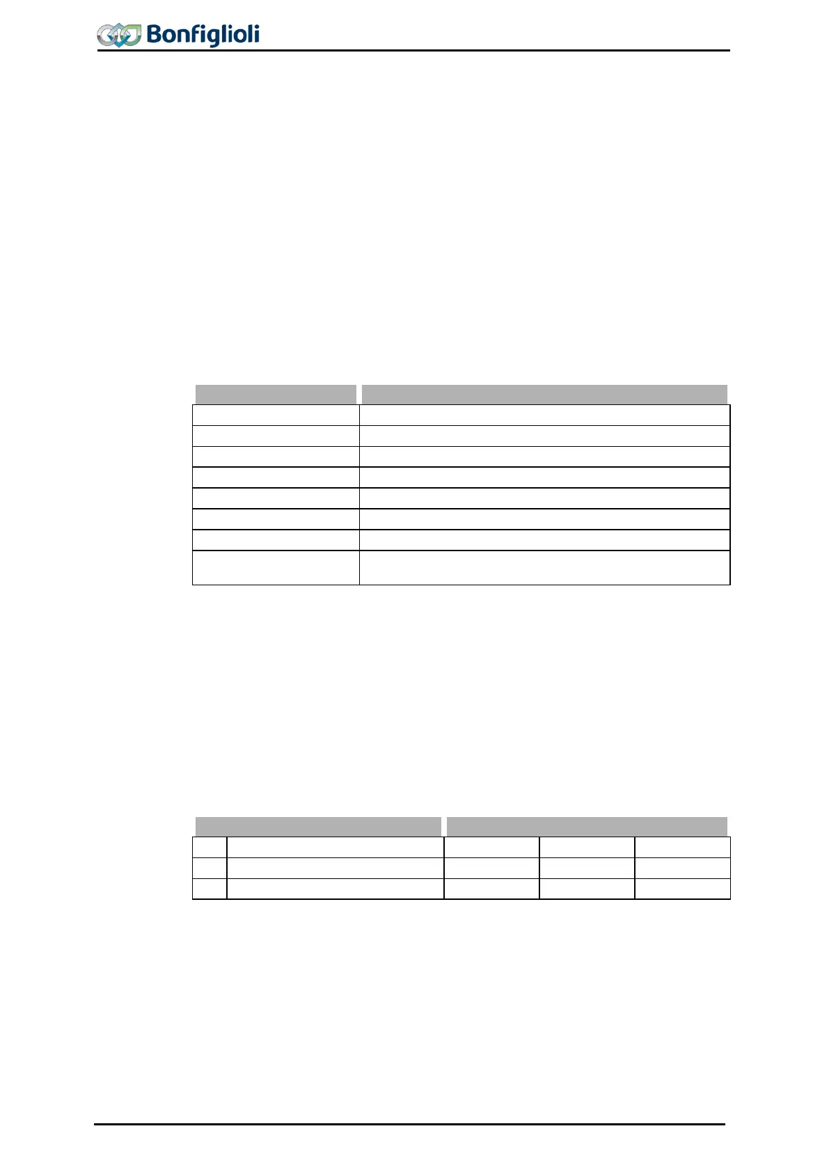
No.
Description Min. Max. Fact. sett.
574
Power Limit 40.00 % 95.00 % 80.00 %
575
Limitation time 5 min 300 min 15 min
In the operation modes with overload reserve (Ixt) there is a reduction of the output
current when the threshold value is exceeded, with a distinction being made between
long and short-term overload reserve. After the short-
term overload (1 s) has been
used up, the output current is reduced to the long-term overload
the present switching frequency. After the long-
term overload current has been used
up (60 s), the output current is reduced to the rated current which also depends on
the switching frequency.
210 Operating Instructions ACU 06/13

 Loading...