Wire size should be selected in accordance with local codes, according to the
current rating of the braking transistor. Use copper conductors rated 75°C.
In general, the wire type should be selected by the nominal system AC
voltage and the continuous current rating of the module.
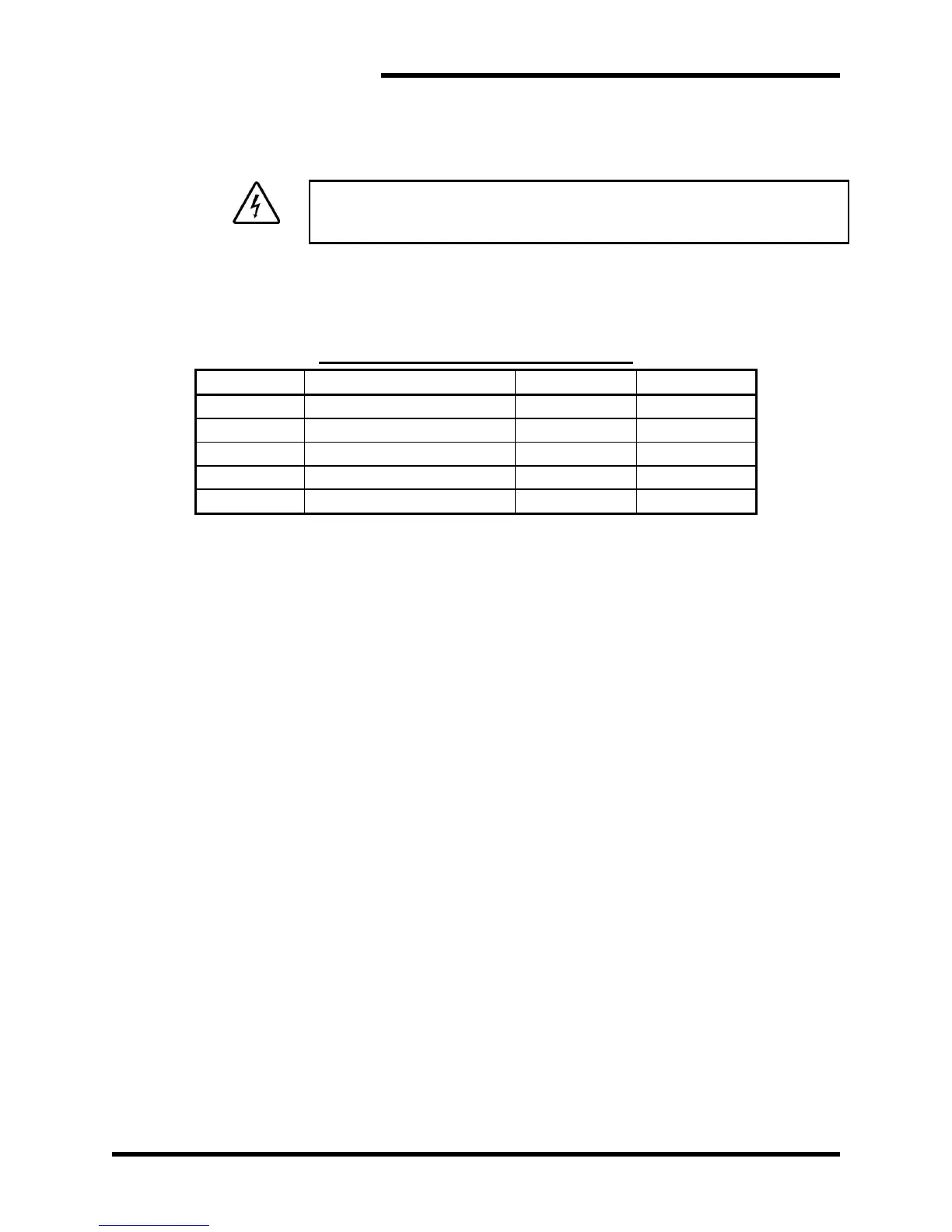
Table 3-1: Power Wiring Specifications
3.4.1.1. DC BUS CONNECTION
As a general rule of thumb, 30 feet (10m) is the maximum total buswork
or cable that the chopper should be mounted from the drive. This means
that the actual installation distance should be 15 feet (5m), as the cable
must go out and back. If you must connect the choppers farther away,
see Section 6.6.
The braking transistor must be connected directly to the DC bus filter
capacitors of the drive.
Figure 3-10 is an example of the terminals that may be available in your
installation. Not all of the terminals may be on your drive. Refer to the
drive manufacturer's manual or technical documents to locate the proper
terminals. Your drive will have different terminal markings depending on
manufacturer and drive series.
Ensure that the polarity of the connection is correct. Incorrect polarity will
effectively short the DC bus of the drive, and can cause severe damage
to the drive, load resistor, and the Bonitron braking transistor.
The proper terminals to attach the braking transistor are marked + and -
on Figure 3-10.
The terminals marked BR+ and BR- are intended for the internal braking
transistor. If the Bonitron external braking transistor is hooked to the
terminals, the braking transistor will not operate properly. In some cases,
it may cause drive failure.
The terminals marked X and Y are intended for connection of a DC link
choke. If the Bonitron braking transistor is connected to the terminals
marked "X" and "-" in Figure 3-10, switching resonances caused by the
DC link choke will destroy the braking transistor. If the Bonitron braking
transistor is connected between X and Y, the drive will not operate.