M3452 vR8 EIP/PDP
34
4.2.5. FAULT MODES
Faults are indicated in two ways. The green Control Power LED on the front
of the module will flash, and a fault bit will be set in the Fault Word on the
network. When there is any unrecoverable fault, the Status output will open.
(Section 4.2.2.6)
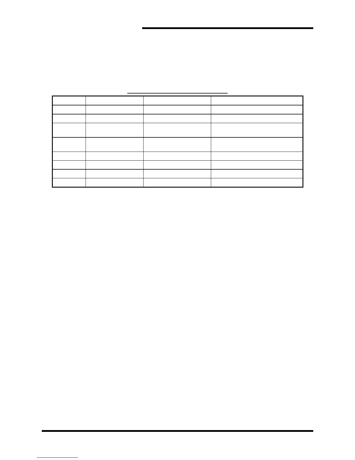
Table 4-1: Fault Conditions Table
Note: See Section 5 for Troubleshooting.
4.2.5.1. FAULT FLAGS
Word 1 of output data represents flags for each individual system fault.
Bit 0 is the least significant bit.
4.2.5.1.1. LOGIC VOLTAGE – BIT 0
This indicates that the onboard control power is not operating
properly. One of the power supplies on the control board has failed,
and the braking module cannot regulate the DC bus.
If the supply voltage returns to normal, this fault can be reset with
the reset bit (Section 4.2.4.2.1.3) or the reset input (Section 4.2.2.4).
4.2.5.1.2. OVERTEMP – BIT 1
This contact indicates that the module’s heatsink is outside
operating temperature. If the heatsink gets too hot to safely operate,
the module will stop braking control and this bit will go high. Once
the temperature of the heatsink falls to a safe operation temperature,
the module will begin braking action again, and this bit will go low.
For 1600 amp modules, the shutdown temperature is 180°F, for all
others the shutdown temperature is 160°F.
4.2.5.1.3. MASTER/SLAVE MISMATCH – BIT 2
If more than one master is configured on a system, the braking
modules configured as masters will sense extra pulses on the
control signal lines and stop operating. This bit will go high.
Reconfigure the system to have only one master. (Section 4.2.3)
This fault can be reset with the reset bit (Section 4.2.4.2.1.3) or the
reset input (Section 4.2.2.4).