User’s Manual
43
5. MAINTENANCE AND TROUBLESHOOTING
Repairs or modifications to this equipment are to be performed by Bonitron approved
personnel only. Any repair or modification to this equipment by personnel not approved
by Bonitron will void any warranty remaining on this unit.
5.1. PERIODIC TESTING
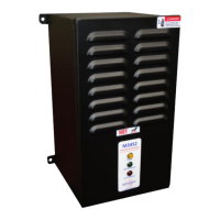
At least every other month, visually inspect the front panel indicator lights to be sure
they are operating correctly. With control power applied, the green Control Power
indicator should be illuminated. The amber DC Bus indicator will be on if the drive
bus is above 50VDC. The red Active Braking indicator will only be on or flashing if
the module is switching energy from the DC bus. There are no operational tests to be
performed.
5.2. MAINTENANCE ITEMS
Monthly, check the module for buildup of dust, debris, or moisture. Dangerous
voltages exist within the module and the buildup of dust, debris, and moisture can
contribute to unwanted arcing and equipment damage. Take whatever corrective or
maintenance actions are necessary to keep the module clean and moisture free.
Monthly, check the cooling fan and heatsink for any buildup of debris. If they require
cleaning power down the drive system and blow the debris out with clean dry air as
necessary to maintain proper cooling performance. Note: After blowing out the fan
and/or heatsink, blow off any dust or debris that may have gotten on any of the circuit
boards.
5.3. TROUBLESHOOTING
Lethal voltages exist in these systems! Before attempting checks or repair,
follow all precautions to ensure safe working conditions, including lockout /
tagout procedures, and verifying safe working voltages with proper meters.
Do not rely on the DC Bus indicator to ensure a safe condition.
Only qualified personnel familiar with variable frequency AC drives and
associated machinery should plan or implement the installation, start-up,
and subsequent maintenance of the system. Failure to comply may result
in personal injury, death, and / or equipment damage!
Feel free to call Bonitron any time the equipment appears to be having problems.
5.3.1. GREEN CONTROL POWER LIGHT NOT ILLUMINATED
Check control voltage input level on customer terminal TB1-1&2. Refer
to Table 2-1: Control Voltage Rating and be sure it is within the specified
range. The modules can be ordered with various control voltages, and
the proper voltage must be used for the module’s configuration.
Check if the status of the Logic Voltage bit is set. This would indicate
insufficient logic voltage. This can be caused by a failure in the control
circuit. The module will need repair.
If the control voltage is correct and status contacts are closed, the
indicator may be burned out, and need replacement.