User’s Manual
39
4.2.6.2. PROFIBUS DP
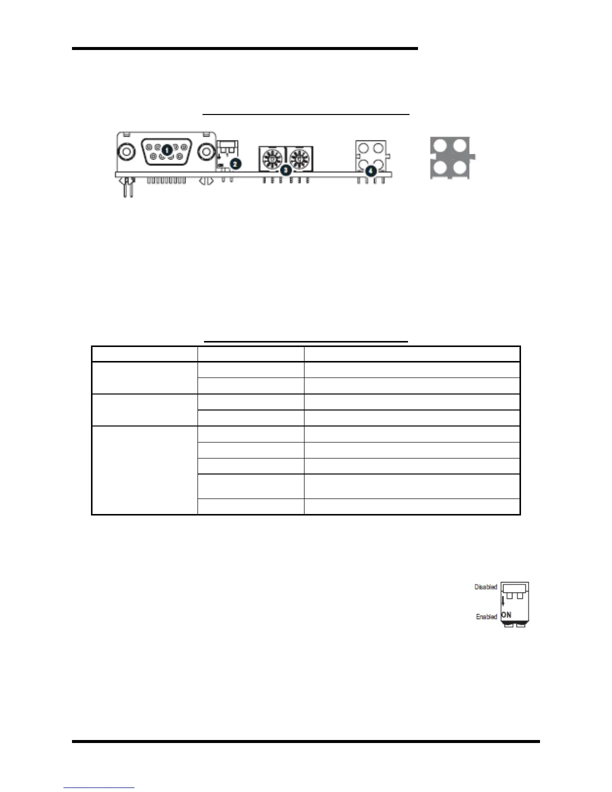
Figure 4-4: PROFIBUS Module Features
4.2.6.2.1. PROFIBUS STATUS INDICATORS
These LEDs indicate run time status and errors to the user. During
power up, a LED test sequence is performed according to the
EtherNet / IP specification.
Table 4-3: PROFIBUS Status Indicators
Bus online, data exchange possible
Bus not online (or no power)
Bus not offline (or no power)
No diagnostics present (or no power)
Error in Configuration Data
Error in initialization of the PROFIBUS
communication ASIC
Watchdog timeout (internal error)
4.2.6.2.2. PROFIBUS CONFIGURATION SWITCHES
4.2.6.2.2.1. TERMINATION SWITCH
Each bus segment in a PROFIBUS network must be
terminated properly to ensure error-free operation. If the
module is used as the first or last node in a
network segment, the termination switch
must to be in ON position. If the module is in
the middle of a network, the switch has to be
in OFF position.
Note: If an external termination connector is used, the switch
must be in OFF position
4.2.6.2.2.2. NODE ADDRESS SWITCHES
These rotary switches can be used to set the node address
of the module in the range 0...99. The switches are read only