M3452 vR8 EIP/PDP
40
during startup. If the setting is changed, the module will have
to cycle power for the change to have effect.
4.2.6.2.3. MODULE CONFIGURATION
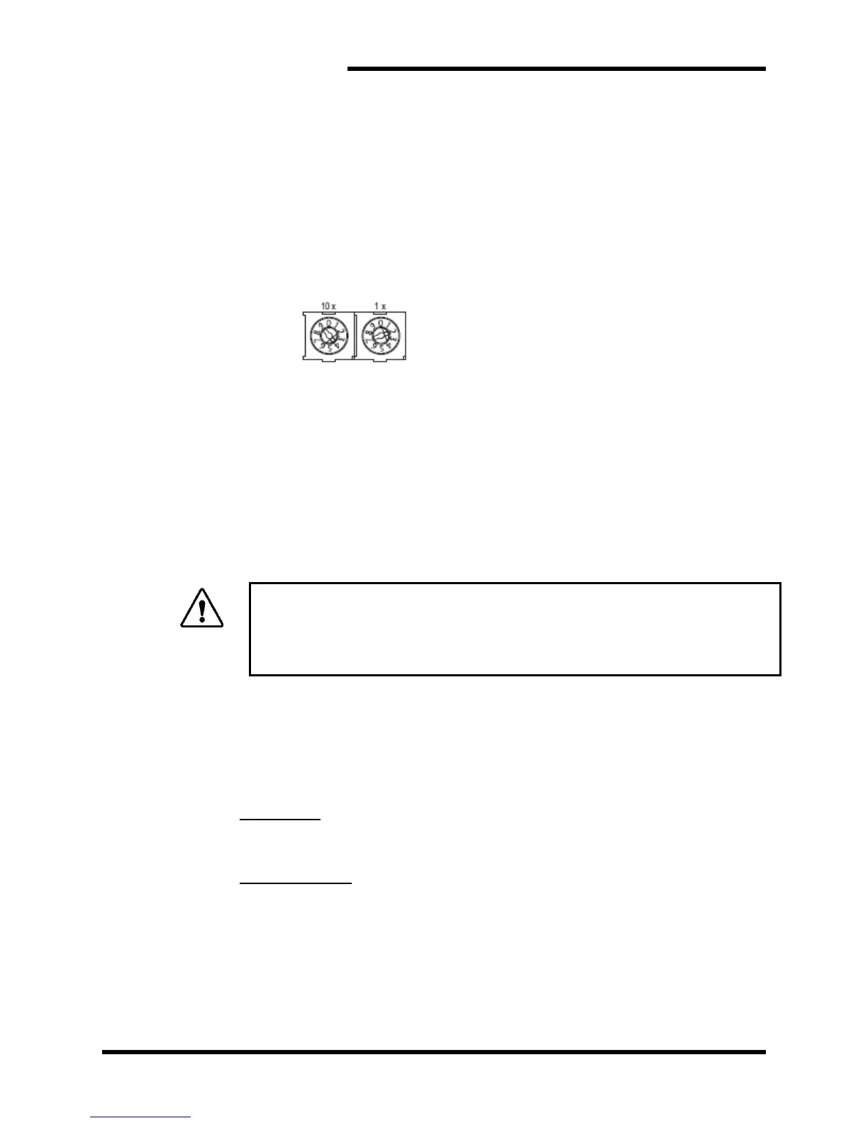
The module’s network address is configured by the two rotary
switches on the front of the network module. The module can be
assigned any address between 0 and 99, with the left switch
representing the most significant digit. The module’s address
cannot be changed while the module is active. If the address is
changed, the unit must be powered off and back on for the changes
to take effect.
Example: When the left switch is set to 4 and the right one is set to
2, the final value will be 42.
4.2.6.2.4. PLC CONFIGURATION
The GSD file for the network module may be found by visiting the
Bonitron website. Load the GSD file onto your PLC according to
your PLC manufacturer’s instructions. Configure both the input and
the output data ranges to a size of 128 bytes, and the RPI time to
100 mS.
4.3. STARTUP
Bonitron dynamic braking transistor modules are designed to be used with
stand-alone or common DC bus drive/inverter systems with bus capacitors.
When using the Bonitron modules on common bus systems, special
considerations may apply. Review the Application Notes in Section 7 prior
to start-up!
4.3.1. PRE-POWER CHECKS
Ensure that all connections are tight, DC bus polarity is correct, and that all
field wiring is of the proper size for operational requirements. Check for
exposed conductors that may lead to inadvertent contact. Verify the load
bank is properly sized for the application. The ohms value and wattage rating
of the load bank are important for proper and reliable system operation!
Remember: do not operate the module with less than its minimum ohms
value rating! Verify that the Master / Slave jumpers are in their proper
position for intended use.
MASTER/SLAVE
All modules come from the factory set in Slave mode. If the module is the
only module used in the system, it should be set as Master. Place a jumper
between TB2-7&8 for stand-alone systems or systems that have a static
Master. In systems that have multiple units, refer to Section 4.2.3 for more
information on setting up systems with multiple units.