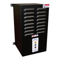
4.2.4.2. INPUTS
Words 0-1 of input data are control registers for the braking module. Word
0 is the least significant word.
4.2.4.2.1. CONTROL BITS
The bits of word 0 of input data represent the controllable status
flags for the braking unit. Bit 0 is the least significant bit.
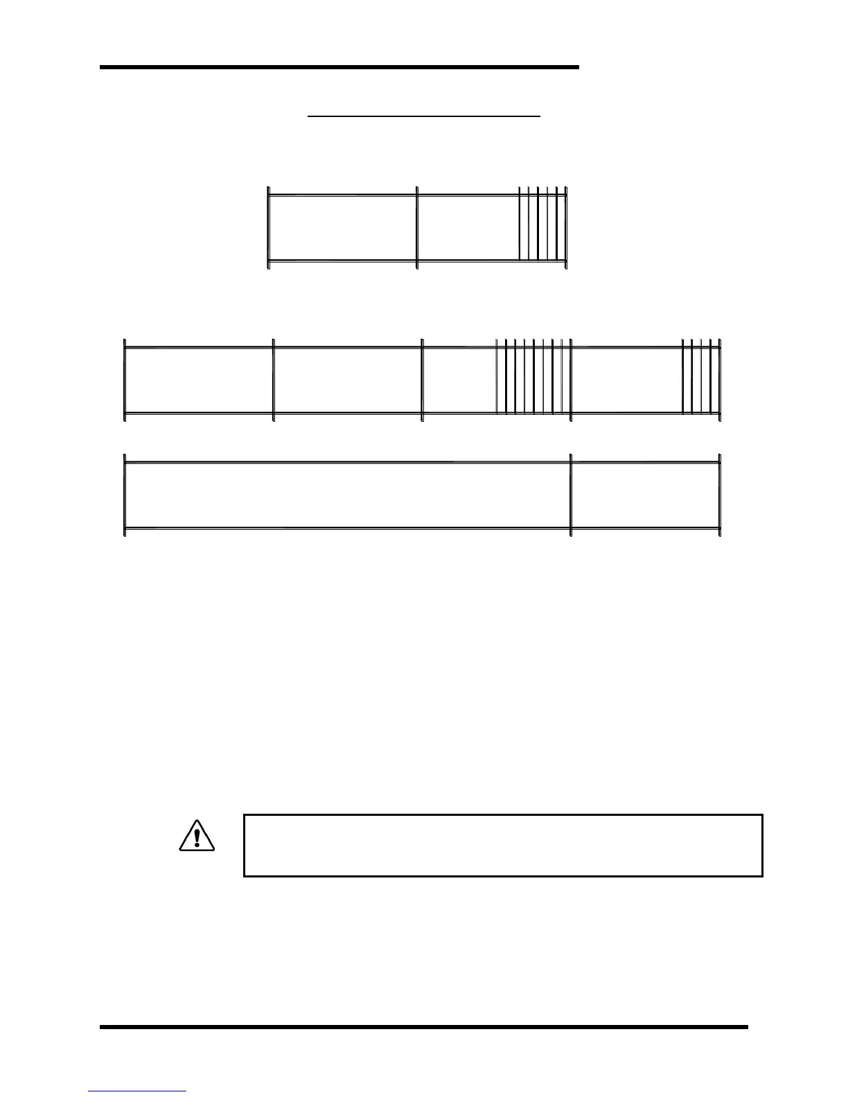
4.2.4.2.1.1. ENABLE – BIT 0
Setting bit 0 enables the braking unit. The hardware enable
terminal (4.2.2.2) must also be closed for the unit to be active.
4.2.4.2.1.2. DISCHARGE - BIT 1
Setting bit 1 sends a discharge command to the braking unit.
The hardware discharge terminal (4.2.2.3) must also be
closed to initialize a discharge.
The discharge input causes the IGBT to go on full until the input is removed.
This can cause severe overheating in the load resistor if input power is not
removed from the DC bus!
4.2.4.2.1.3. RESET - BIT 2
Setting bit 2 sends a reset command to the braking unit. The
hardware reset terminal (4.2.2.4) does not need to be closed
for the unit to reset the braking unit.