User’s Manual
17
If the braking transistor is connected to the terminals marked "A" and "B"
in Figure 3-10, switching resonances caused by the lack of filter
capacitance during precharge will destroy the braking transistor.
3.4.1.2. RESISTOR CONNECTION
The polarity of the resistor connections is not important; however, it is
critical that the resistor be connected to the proper terminals. Improper
hookup can lead to the resistor being connected directly across the DC
bus, which will cause severe overheating and drive stress.
3.4.1.3. GROUNDING REQUIREMENTS
All units come equipped with either a ground terminal or ground stud that
is connected to the module chassis. Ground the chassis in accordance
with local codes. Typically, the wire gauge will be the same as is used to
ground the attached drive.
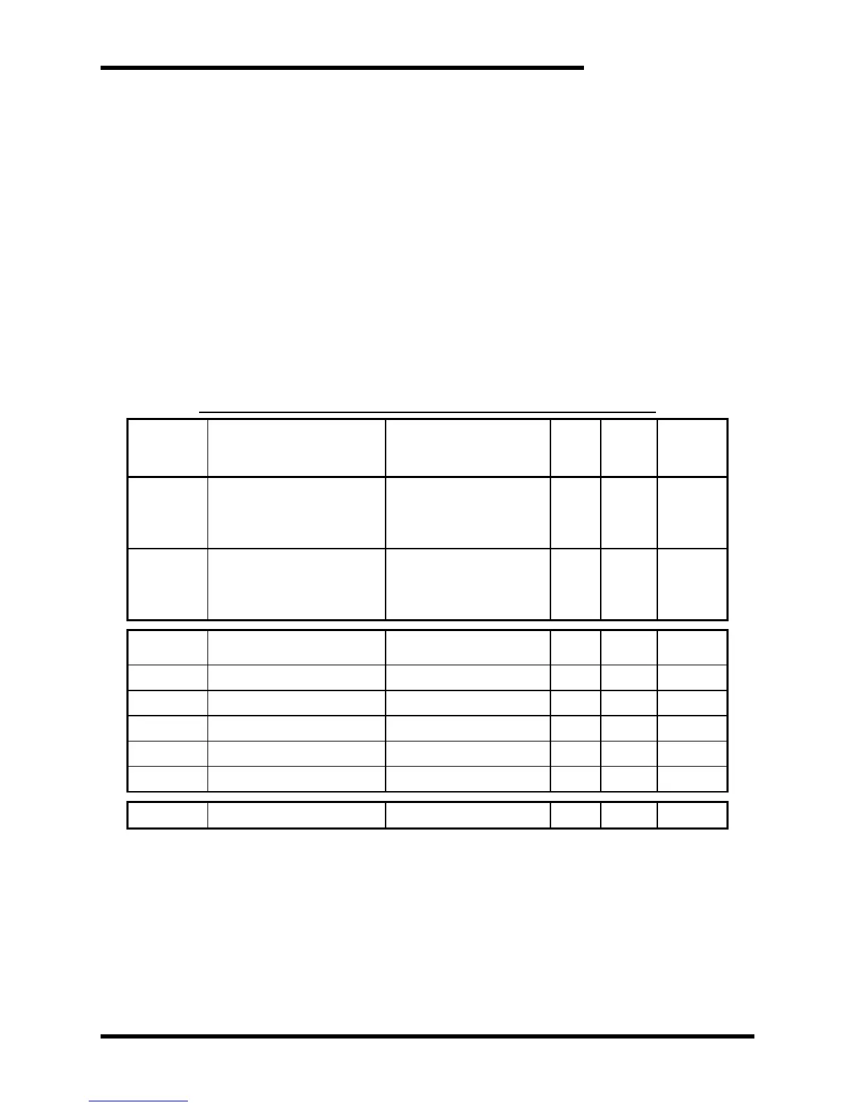
3.4.2. I/O WIRING
Table 3-2: I/O Terminal Block Specifications: R8 Control Board