M3452 vR8 EIP/PDP
4
1. INTRODUCTION ..........................................................................................................................7
1.1. Who Should Use ........................................................................................................................... 7
1.2. Purpose and Scope ........................................................................................................................ 7
1.3. Manual Version and Change Record ............................................................................................ 7
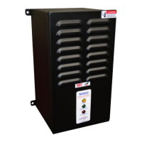
Figure 1-1: Typical M3452 – R8 ................................................................................................................. 7
1.4. Symbol Conventions Used in this Manual and on Equipment ..................................................... 8
2. PRODUCT DESCRIPTION ............................................................................................................9
2.1. Related Products ........................................................................................................................... 9
2.2. Part Number Breakdown ............................................................................................................ 10
Figure 2-1: M3452 Part Number Breakdown ............................................................................................ 10
Table 2-1: Control Voltage Rating ............................................................................................................ 10
Table 2-2: Available Braking Current Ratings .......................................................................................... 10
Table 2-3: DC Bus Voltage Rating ............................................................................................................ 11
Table 2-4: Chassis Codes ........................................................................................................................... 11
Table 2-5: Control Option Codes ............................................................................................................... 11
2.3. General Specifications ................................................................................................................ 12
Table 2-6: General Specifications .............................................................................................................. 12
2.4. General Precautions and Safety Warnings ................................................................................. 13
3. INSTALLATION INSTRUCTIONS ................................................................................................15
3.1. Product Inspection ...................................................................................................................... 15
3.2. Site Selection .............................................................................................................................. 15
3.3. Mounting .................................................................................................................................... 15
3.4. Wiring and Customer Connections ............................................................................................. 16
3.4.1. Power Wiring ........................................................................................................................... 16
Table 3-1: Power Wiring Specifications .................................................................................................... 16
3.4.2. I/O Wiring ............................................................................................................................... 17
Table 3-2: I/O Terminal Block Specifications: R8 Control Board ............................................................ 17
Figure 3-1: Customer Connections in K6 Chassis ..................................................................................... 18
Figure 3-2: Customer Connections in K9 Chassis ..................................................................................... 19
Figure 3-3: Customer Connections in K10 Chassis ................................................................................... 20
Figure 3-4: Customer Connections in M14 Chassis .................................................................................. 21
Figure 3-5: Customer Connections in T10 Chassis.................................................................................... 22
3.5. Typical Configurations ............................................................................................................... 23
Figure 3-6: Master Stand-Alone Hookup................................................................................................... 23
Figure 3-7: Master with Slave(s) Hookup.................................................................................................. 23
Figure 3-8: I/O Hookup ............................................................................................................................. 24
Figure 3-9: Equivalent Input/Output Diagrams ......................................................................................... 24
Figure 3-10: Braking Transistor Customer Connections ........................................................................... 25
4. OPERATION ..............................................................................................................................27
4.1. Functional Description ............................................................................................................... 27
4.2. Features ....................................................................................................................................... 27
4.2.1. Indicators ................................................................................................................................. 27
4.2.2. Terminal Strip I/O ................................................................................................................... 27
4.2.3. Master / Slave Control (200 Amp to 1600 Amp) .................................................................... 29
4.2.4. Fieldbus I/O ............................................................................................................................. 30
Figure 4-1: 3452R8 Memory Map ............................................................................................................. 31
Figure 4-2 Setpoint Adjustment Range ...................................................................................................... 32
4.2.5. Fault Modes ............................................................................................................................. 34
Table 4-1: Fault Conditions Table ............................................................................................................. 34