EasyManua.ls Logo

Bosch BEA 350 User Manual

Bosch BEA 350
103 pages
To Next Page IconTo Next Page
Page #1 background imageLoading...
Page #1 background image
1
Repair Instructions
Bosch Emissions Analysis
BEA 150
BEA 250
BEA 350
In conjunction with Service
software for PC

Table of Contents

Question and Answer IconNeed help?

Do you have a question about the Bosch BEA 350 and is the answer not in the manual?

Bosch BEA 350 Specifications

General IconGeneral
BrandBosch
ModelBEA 350
CategoryMeasuring Instruments
LanguageEnglish

Summary

Important Information

Compulsory Calibration

Regulations governing the calibration of exhaust-gas analyzers.

Brief Description of Unit Functions and Servicing

Exhaust-gas Analyzer Module

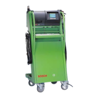
Description of the analyzer module and its functions.

Servicing the Unit

Maintenance procedures for the unit.

Checking the AMM Exhaust-Gas Analyzer Module

NO-Sensor

Functions for the NO measuring sensor.

Checking Opacimeter RTM 430

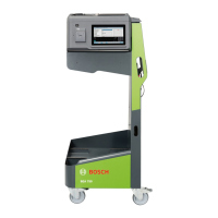
Test the opacimeter RTM 430.

Checking the PCB and Periphery of the BEA Control Module

Checking the Engine-Speed and Temperature Measuring Module (DTM)

Checking Oil Temperature and Engine Speed in Diesel Diagnosis

Check oil temp and engine speed in diesel diagnosis.

Checking Oil Temperature and Engine Speed in Petrol Diagnosis

Check oil temp and engine speed in petrol diagnosis.

Checking the Ignition Point and Dwell Angle

Check ignition point and dwell angle.

Trouble-Shooting by Message Number

General Messages

General malfunction messages and remedies.

Messages about Boot Test Functions

Malfunction messages related to boot test.

Messages about Software Installation Functions

Malfunction messages for software installation.

Messages about EAM Exhaust-Gas Analyzer Module

Malfunction messages for EAM module.

Adjustment Functions

Setting the Maintenance Interval

Set the maintenance interval in days.

Setting the Calibration Interval

Set the calibration interval.

Repairs

Adjusting Mains Voltage for Toroidal Mains Transformer

Adjust mains voltage for transformer.

AC / DC Voltage Supply to Control Module PCB

Check voltage supply to control module PCB.

Replacing the Measuring Bank

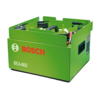
Procedure to replace the measuring bank.

Install New O2 Sensor

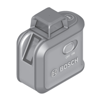
Install and calibrate a new O2 sensor.

Replacing the Pump

Procedure to replace the pump.

Replacing the Pressure Sensor

Procedure to replace the pressure sensor.

Replacing the NO Sensor

Procedure to replace the NO sensor.

Replacing the Control Module PCB

Procedure to replace control module PCB.

Replacing the OBD Circuit Board

Procedure to replace OBD circuit board.

Related product manuals