49
i In order to check the ignition point and
the dwell angle, you will require the TD/
TN/Term1 connection cable, Part
No.: 1 684 460 196 (SZB) and timing
light 1 687 022 767 (SZB).
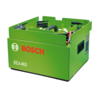
1. Press F2 or u to go to the menu
Ignition point/Dwell angle and
open it by pressing F5 >> or E.
2. In the No. of pulses menu, set the
number of pulses to 1 using the o or u
keys.
rot
schwarz
Best. -Nr.
Lötseite
1
2
3
4
5
13
5
2
4
465463Ha
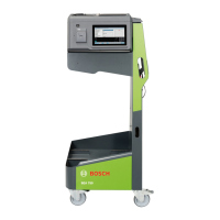
6.3 Checking V-lambda
6.3.1 Terminal diagram of
V-lambda cable
6.4 Checking the ignition point and
dwell angle
red
Solder side
black
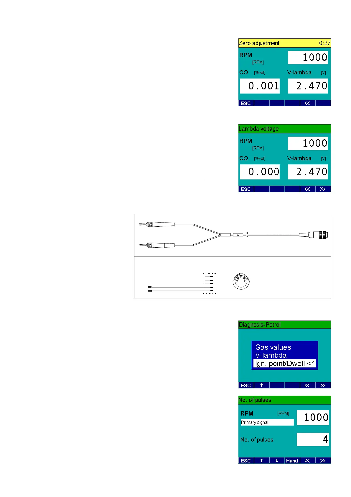
First of all, automatic zero calibration takes
place.
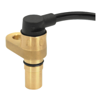
3. Connect the clip-on trigger sensor to
the BEA.
4. Clamp the clip-on trigger sensor over
the loop of your P 100.
5. Connect the B-cable of the BEA to the
B-jack of your P 100.
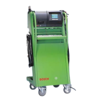
6. Connect the V-lambda cable to volta-
ge output V, C, R and rR of your P 100.
7. Connect a digital multimeter parallel
to this.
8. Set the voltage to 2.500 V.
9. Compare the value on your digital
multimeter with the value displayed on
the BEA.
Nominal value: 2.500V
+ 0.1V