50
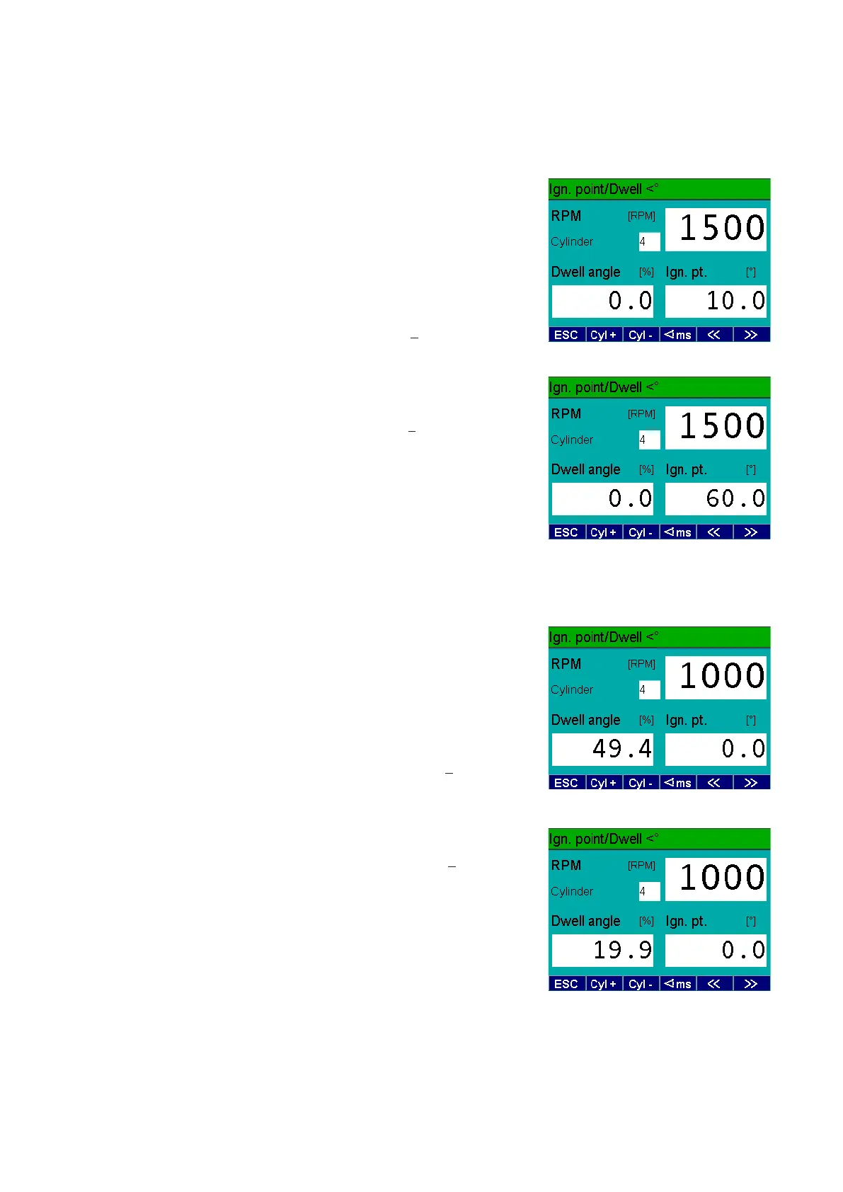
6.4 Checking the ignition point and
dwell angle
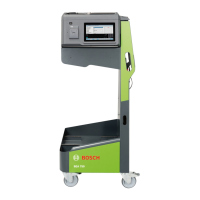
6.5 Checking the dwell angle
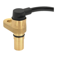
3. Connect the clip-on trigger sensor to
the BEA.
4. Clamp the clip-on trigger sensor over
the loop of your P 100.
5. Connect the B-cable of the BEA to the
B-jack of your P 100.
6. Switch on the P 100. The timing light
begins to flash.
7. Flash the timing light at the photo
diode in the P 100 and set the ignition
point to 10°crankshaft using the ad-
justing wheel of the timing light.
8. Compare the value on your P 100 with
the value displayed on the BEA.
Nominal value:
10°crankshaft
+ 0.5°crankshaft
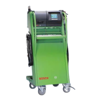
9. Repeat the test with an ignition point
of 60°crankshaft
Nominal value:
60°crankshaft
+ 0.5°crankshaft
i Use F3 to change the dwell angle
between %, ms or degrees (°).
1. Connect the Term.1 connection cable
(green banana plug) to the Term.1
jack of your P 100.
2. Connect the B-cable of the BEA to the
B-jack of your P 100.
3. On your P 100, set an engine speed
of 1000 rpm.
Then set the P 100 to a dwell angle
of 50%.
Nominal value: 50%
+ 0.5%
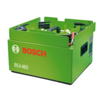
4. Repeat the test with a dwell angle
of 20%
Nominal value: 20%
+ 0.2%