32
5. Checking the PCB and
periphery of the BEA con-
trol module
5.1 Checking the interface for DTM
To check the interfaces of the control module PCB, you will require the following shorting
plugs:
z 15-way subminiature Cannon connector for RTM interface (self-made, see Sec. 5.2)
z 20-way Micro-Match plug (new)
z 10-way Micro-Match plug (new)
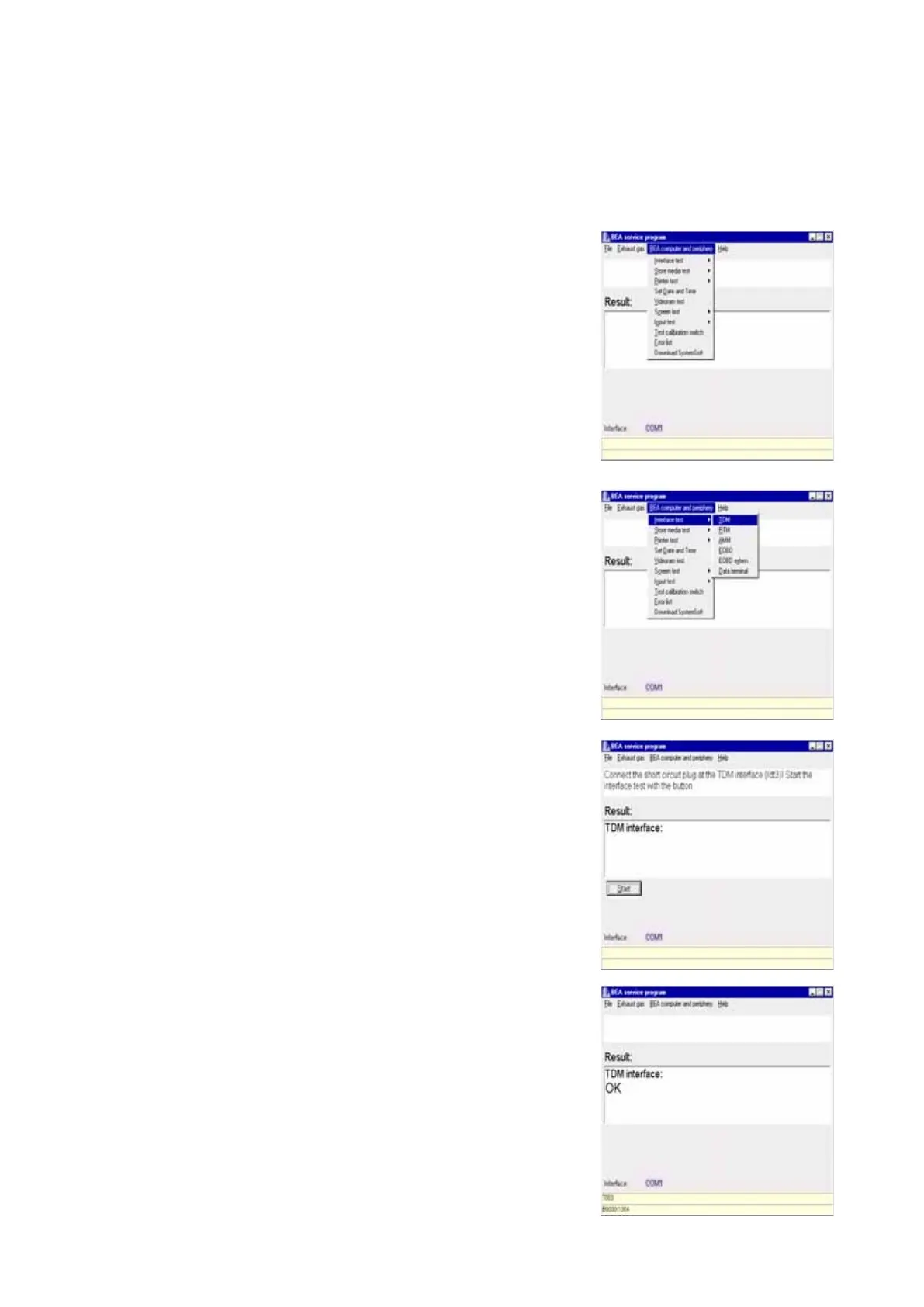
Open the menu BEA computer and pe-
riphery.
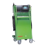
Select the Interface test menu and then
DTM.
Remove the 20-way Micro-Match plug
from X8 of the control module PCB.
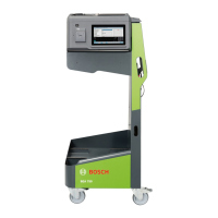
Plug the 20-way shorting plug into X8 of
the control module PCB.
Start the interface test by double-clicking
the mouse or pressing Enter E.
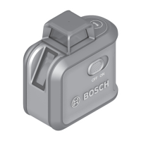
If the interface test is error-free, the
message OK appears in the results box.
If the interface test is unsuccessful, an
error message is displayed.
For example: B0246:1300.
1300 = No shorting plug inserted or pins
3 and 5 of shorting plug not
jumpered.
If any error messages other than this one
are displayed, the control module PCB
must be replaced (Sec. 10.27).