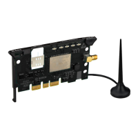
Hardware
2--11
1070 072 196-101 (00.06) GB
20 mA Interface
Signal level and assignment of the connectors comply with the guidelines:
”VDI Richtlinien 2880, Blatt 2” for programmable logic controllers, process
and data interfaces (limitation: max. reverse voltage 27 V). The 20 mA inter-
faces can be, in dependence on the pin assignment, switched to active, i.e.
with source of current, or to passive.
Line Statuses
D logic 1 20 mA
D logic 0 no current
20 mA active
Explanation Designation Pin No. Signal Direction
Shield Shield Housing
Received data + PLC RxD + 12
Received data -- PLC RxD -- 24
Transmitted data + PLC TxD + 13
Transmitted data -- PLC TxD -- 25
Data Set Ready + DSR + 14
Data Set Ready -- DSR -- 18
Reader Control + RDRCTL + 16
Reader Control -- RDRCTL -- 21
For active operation, the connections 9 (12 V in) and 10 (12 V out) must be
jumpered.
20 mA passive
Explanation Designation Pin No. Signal Direction
Shield Shield Housing
Received data + PLC RxD + 22
Received data -- PLC RxD -- 12
Transmitted data + PLC TxD + 23
Transmitted data -- PLC TxD -- 13
Data Set Ready + DSR + 11
Data Set Ready -- DSR -- 14
Reader Control + RDRCTL + 19
Reader Control -- RDRCTL -- 16
 Loading...
