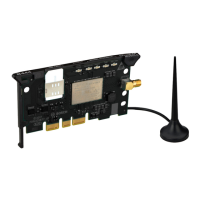
General Information Regarding BUEP-E and BUEP19E
7--8
1070 072 196-101 (00.06) GB
Coordination
Parameter
Contents
Word
High Byte Low Byte
PW13 Process coordination point Field coordination marker
Example 02
H
FF
H
I/O status No coordination marker
The parameter coordination is composed of a field coordination marker (low
byte) and a process coordination point (high byte).
It is the coordination markers’ task to coordinate the execution of an instruc-
tion on the PST. It is executed only if the corresponding coordination event is
’true’; for the CL500, this means, that you must be in the process coordina-
tion point or that the field coordination marker must be set to 1; the same is
applicable to other controllers.
Controller Type CL500 as PST
The command ’control central unit’ in the CL500 system uses two kinds of
coordination markers:
D Process coordination marker (AKM) and
D for ZS501 and up: Field coordination marker (FKM)
TheAKMsaresetasfollows:
D 00
H
System STOP status
D 01
H
System RUN status
D 02
H
I/O status
D 03
H
I/O status or STOP
D 04
H
EP
D 05
H
EP or STOP
D 06
H
OM1
D 07
H
OM1 or STOP
D FF
H
No process coordination
The FKMs in the special marker area are determined as follows:
D SM16.0 to SM17.7: one-time FKMs
These FKMs are reset by the system after execution of the coordinated
command.
D SM18.0 to SM19.7: permanent FKMs
These FKMs are not reset by the system after execution of the coordi-
nated command.
The FKMs are coded as follows:
D SM16.0 to SM 17.7: FKMs 0
H
to F
H
D SM18.0 to SM 19.7: FKMs 10
H
to 1F
H
D No field coordination: FKMs FF
H
 Loading...
