4. Voting/Control inputs - Connect DCN-FMICB Microphone Control Panels, DCN-FPRIOB
Microphone Priority Panels and DCN-FV(CRD) Voting Panels to the dual delegate
interface.
5. Lid - Gives access to the controls inside.
6. Audio inputs - Connects external audio sources to the dual delegate interface.
7. Audio outputs - Connects loudspeakers to the dual delegate interface.
8. DCN socket - Makes a loop-through in the DCN with the dual delegate interface.
The following sections give more information about the mentioned subject:
– Connection: DCN-DDI Dual Delegate Interface, page 133.
– Configuration: DCN-DDI Dual Delegate Interface, page 213.
– Technical Data: DCN-DDI Dual Delegate Interface, page 282.
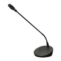
DCN-FMIC Microphone Connection Panel
The DCN-FMIC Microphone Connection Panel connects DCN-MICL and DCN-MICS Pluggable
Microphones to the DCN-DDI Dual Delegate Interface.
Figure 3.33: Microphone connection panel
The microphone connection panel contains:
1. Output level plug - Connects the microphone connection panel to a DCN-FCS Channel
Selector to prevent acoustic feedback.
2. Microphone socket - Connects a DCN-MICL or DCN-MICS Pluggable Microphone to the
microphone connection panel.
3. Solder spot - Enables or disables the green LED ring of the connected DCN-MICL or DCN-
MICS Pluggable Microphone.
The following sections give more information about the mentioned subject:
– Installation: DCN-Flush mounted products, page 103.
– Connection: DCN-FMIC Microphone Connection Panel, page 135.
– Configuration: DCN-FMIC Microphone Connection Panel, page 218.
– Technical Data: DCN-FMIC Microphone Connection Panel, page 283.
3.15
40 en | System Overview Conference System
2013.11 | V2.0 | DCN-NG_OM_V4.x Operation Manual Bosch Security Systems B.V.