en
|
50
|
User guide
| OBD 1350
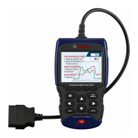
ProGrade OBDII Scan Tool
580001 | REV. A | 11.2016
PID PID Description
SECOND AIR Secondary Air Status
ST FTRM Fuel Trim Bank / Sensor
ST FTRM1, 3 Short Term Fuel Trim1 or 3
ST FTRM2, 4 Short Term Fuel Trim2 or 4
ST SEC
FT1, 2, 3, 4
Short Term Secondary O2 Sensor Fuel
Trim 1, 2, 3, 4
TAC_A_CMD, B_
CMD
Commanded Throttle Actuator A Con-
trol, B Control
TAC_A_REL, B_
REL
Relative Throttle A Position, B Position
TCA_CINP, TCB_
CINP
Turbocharger Compressor Inlet Pres-
sure Sensor A, Pressure Sensor B
TCA_CINT, TCB_
CINT
Turbocharger A Compressor Inlet Tem-
perature, Turbocharger B
TCA_COUTT,
TCB_COUTT
Turbocharger A Compressor Outlet
Temperature, Turbocharger B
TCA_RPM, TCB_
RPM
Turbocharger A RPM, B RPM
TCA_TOUTT,
TCB_TOUTT
Turbocharger A Turbine Outlet Temper-
ature, Turbocharger B
TCA_TINT, TCB_
TINT
Turbocharger A Turbine Inlet Tempera-
ture, Turbocharger B
THROT CMD Commanded Throttle Actuator Control
TP G Absolute Throttle Position G
TQ_ACT Actual Engine - Percent Torque
TQ_DD
Driver's Demand Engine - Percent
Torque
TQ_MAX1,
MAX2, MAX3,
MAX4, MAX5
Engine percent torque at
idle point 1, 2, 3, 4, 5
TQ_REF Engine Reference Torque
TROUB CODE Code causing the Freeze Frame
VEH SPEED Vehicle Speed
VGT_A_ACT Variable geometry turbo A position
VGT_A_ACT, B_
ACT
Variable Geometry Turbo A Position,
Turbo B
VGT_A_CMD
Commanded variable geometry turbo
A position
VGT_A_CMD, B_
CMD
Commanded Variable Geometry Turbo
A Position, Turbo B
VGT_A_STAT
Variable geometry turbo A control
status
VGT_A_STAT, B_
STAT
Variable Geometry Turbo A Control
Status, Turbo B
VGT_B_ACT Variable geometry turbo B position
VGT_B_CMD
Commanded variable geometry turbo
B position
VGT_B_STAT
Variable geometry turbo B control
status
VPWR Control Module Voltage
WG_A_ACT Wastegate A position
WG_A_ACT, B_
ACT
Wastegate A Position, B Position
WG_A_CMD Commanded wastegate A control
WG_A_CMD, B_
CMD
Commanded Wastegate A Control, B
Control
WG_B_ACT Wastegate B position
WG_B_CMD Commanded wastegate B control
8 Appendix B—Glossary
A/C:
Air conditioner
A/D:
Analog to digital
A/F:
Air/Fuel ratio. The proportion of air and fuel delivered to
the cylinder for combustion. For example, an A/F ratio of
14:1 denotes 14 times as much air as fuel in the mixture.
Ideally the A/F ratio is 14.7:1.
ABS:
Anti-lock brake system
A/C clutch relay:
The PCM uses this relay to energize the A/C clutch,
turning the A/C compressor on or off.
A/C pressure sensor:
Measures air conditioning refrigerant pressure and
sends a voltage signal to the PCM.
A/C pressure switch:
A mechanical switch connected to the A/C refrigerant
line. The switch is activated (sending a signal to the
PCM) when the A/C refrigerant pressure becomes too
low or high.
Actuator:
Actuators such as relays, solenoids, and motors allow
the PCM to control the operation of vehicle systems.
Air Injection Reaction (AIR) System:
An emission control system operated by the PCM. Dur-
ing cold starts, an air pump injects outside air into the
exhaust manifold to help burn hot exhaust gases. This
reduces pollution and speeds warm-up of oxygen sen-
sors and catalytic converters. After the engine is warm,
the air will either be dumped back to the atmosphere (or
into the air cleaner assembly) or sent to the catalytic
converter.
APP:
Acceleration pedal position (sensor)
ASR:
Acceleration slip regulation
Bank x:
The standard way of referring to the bank of cylinders
containing cylinder #x. In-line engines have only one
bank of cylinders. Most commonly used to identify the
location of oxygen sensors. See O2S, Sensor x, Sensor
x.
BARO:
Barometric pressure sensor. See MAP sensor.
BBV:
Brake boost vacuum (sensor)
BCM:
Body control module
Boost control solenoid:
A solenoid that is energized by the PCM, in order to
control turbo/supercharger boost pressure.
Brake switch signal:
An input signal to the PCM indicating that the brake
pedal is being pressed. This signal is typically used to