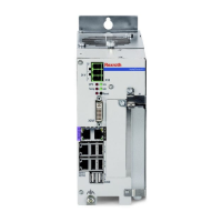
④ Status LEDs and “Reset” button
⑤ Display port connection
⑥ CDI interface (data interface and image
interface)
⑦ Ethernet interfaces
⑧ USB interfaces
⑨ LEDs PF1/PF2 (Sercos III)
⑩ XF01 connection with LEDs L/S
⑪ XF02 connection with LEDs L/S
⑫ XF41 connection with LEDs L/S
⑬ XF40 connection with LEDs L/S
⑭ LEDs PF1/PF2 (RT-Ethernet/Profibus)
⑮ XF08 connection (Profibus)
⑯ Grounding screw (hexalobular T25)
⑰ Hard disk(s)
Fig. 12-1: Front view IndraControl VPB 40.4
12.3 Operating and error displays
There are four LEDs on the connector panel of the IndraControl VPB 40.4 to
display the device states and errors. Apply the specified measure if one of the
following LEDs either indicates an error or a note, see tab. 12-1 "LEDs for
operating and error display on the connector panel" on page 44.
Some LEDs, e.g. the CPU temperature monitoring, are only active if
the service software has been configured accordingly.
LED Display Description Action
V
in
LED green Normal operation –
LED off No supply voltage (24 V DC) Check the supply voltage at
the power supply unit!
TEMP LED off Normal operation –
LED is flashing
red (flashing
frequency
approx. 2 Hz)
Fan is not rotating or is rotating too slowly Check the fan on the control
cabinet PC!
LED is red Overtemperature Reduce the ambient
temperature!
UPS LED off Normal operation –
LED red The control cabinet PC is currently operating
in battery mode, i. e. no supply voltage is
available!
Restore the power supply and
initiate a controlled restart!
Bosch Rexroth AG
Device description
IndraControl VPB 40.4
44/87
DOK-MLC***-INDRACTRLV4-IT02-EN-P
 Loading...


