57
DISASSEMBLY PROCEDURES
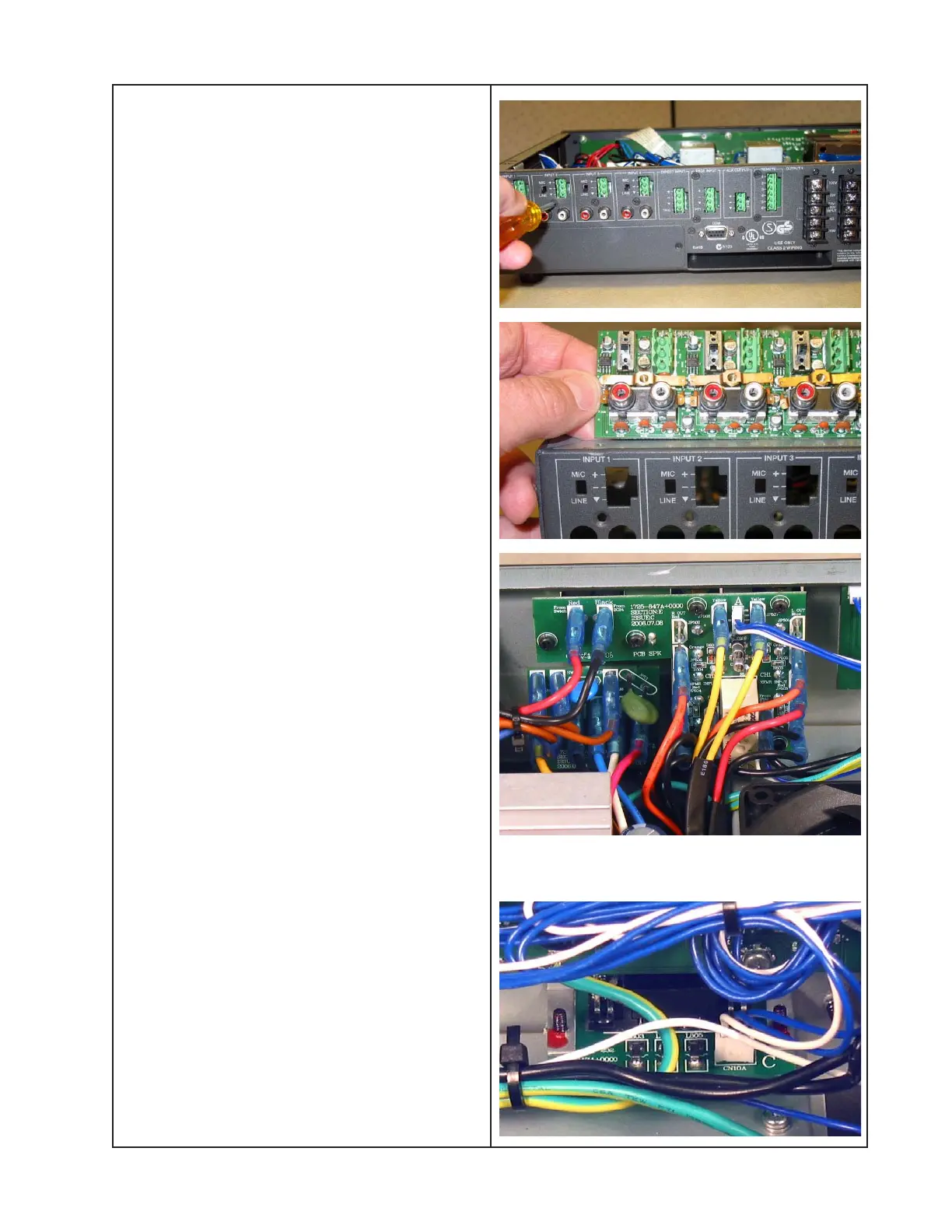
6. Input/Output PCB and RCA Input/AD
Buffer PCB Removal
6.1 Perform procedure 2.
6.2 Remove the eight screws that secure the
Input/Output-RCA Input/AD Buffer PCB
assembly to the back of the chassis. Lift out
the PCB assembly.
Take care to not lose the plastic insulators or
the copper decoupling capacitor yokes
located over the RCA jacks during disas-
sembly.
6.3 Remove the two screws that secure the
RCA Input/AD Buffer PCB to the Input/
Output PCB. Lift off the RCA Input/AD Buffer
PCB.
7. SPKR PCB Removal
7.1 Perform procedure 1.
7.2 Unplug the wiring harness from the DSP
PCB at CN13B.
7.3 Make a note of the wiring configuration
and unplug all of the Faston connectors
from the back of the PCB.
Re-assembly Note: Using the note above,
be sure that all wires are connected to the
correct locations on the SPKR PCB.
7.4 Remove the six screws that secure the
SPKR PCB to the chassis. Lift out the PCB.
8. RS-232 PCB Removal
8.1 Perform procedure 1.
8.2 Unplug the wiring harness from the DSP
PCB at connector CN10B.
8.3 Remove the two jackscrews located on
either side of the DB-9 connector. Remove
the two screws located on either side of the
jackscrew locations. Lift out the PCB.
 Loading...


