58
DISASSEMBLY PROCEDURES
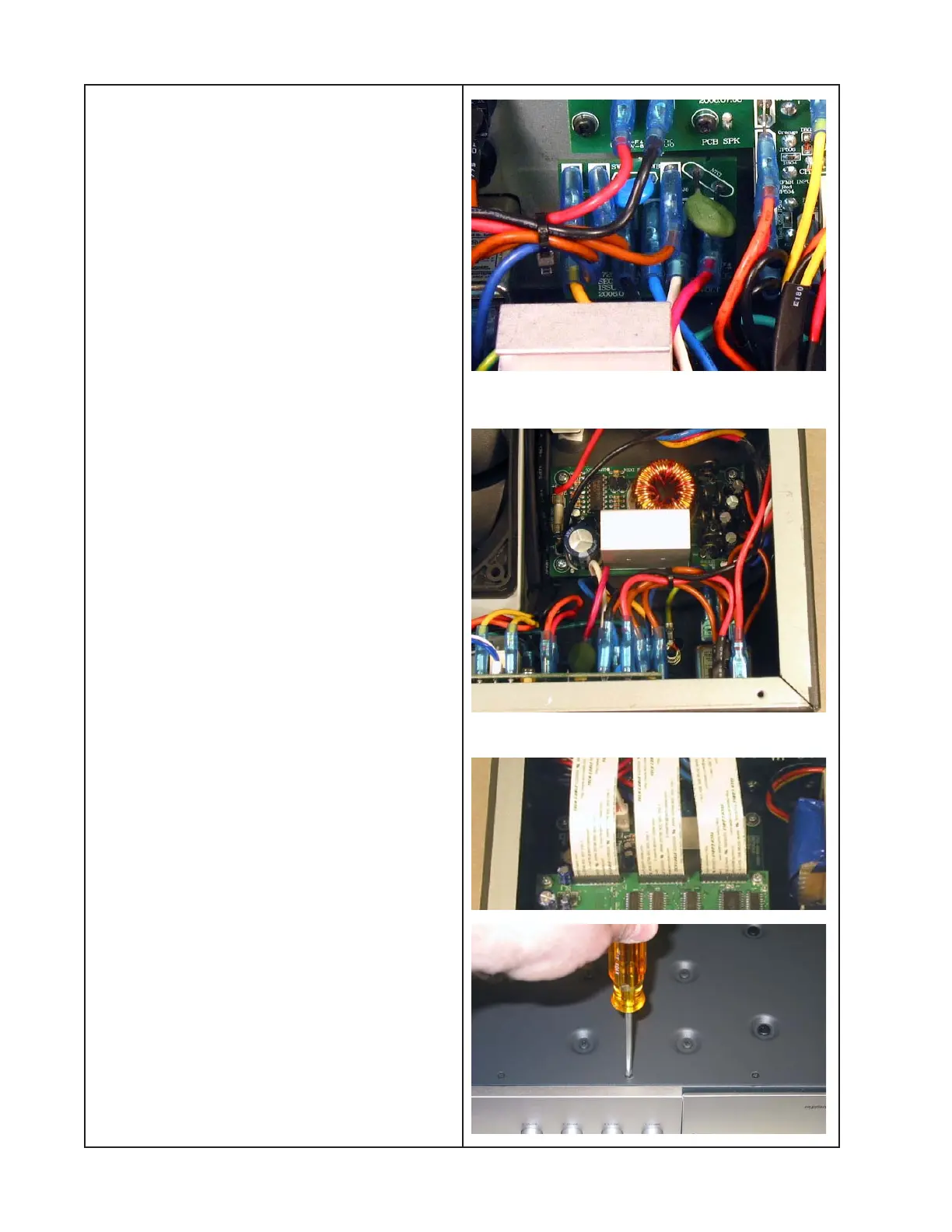
9. Voltage Select Switch PCB Removal
9.1 Perform procedure 1.
9.2 Make a note of the wiring configuration
and unplug all of the Faston connectors
from the back of the PCB.
Re-assembly Note: Using the note above,
be sure that all wires are connected to the
correct locations on the PCB.
9.3 Remove the two screws that secure the
PCB to the back of the chassis.
9.4 Lift out the PCB.
10. DC24 Power Supply PCB Removal
10.1 Perform procedure 1.
10.2 Unplug the red wire from the back of
the power switch. Unplug the black wire
from the SPKR PCB.
10.3 Unplug the DC24 PCB wiring harness
from the PSU PCB at connectors CN16B
and CN17B.
10.4 Remove the four screws that secure
the DC24 PCB to the chassis. Lift out the
PCB.
11. CTRL PCB Removal
11.1 Perform procedure 1.
11.2 Unplug the three ribbon cables from the
DSP PCB at connectors CN08B, CN09B and
CN07B.
11.3 Turn the chassis over top down. Re-
move the five screws located at the front of
the chassis.
 Loading...


