Disassembly / Assembly
Infusomat® Space 6.0 3 - 33EN
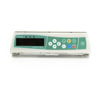
5. Open the connector lock (Fig.: 3 - 31 / Item 2) on the key-
board PCB.
6. Pull the LC display ribbon cable (Fig.: 3 - 31 / Item 1) out of
the connector.
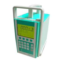
7. Lift the LC display (Fig.: 3 - 32 / Item 1) out of the operating
unit front panel (Fig.: 3 - 32 / Item 4) .
The keyboard screws (Fig.: 3 - 32 / Item 3) must not be loosened.
A special procedure is required to install the keyboard, so that a
uniform pressure point is guaranteed for all keys.
Fig.: 3 - 31
Legend of fig. 3 - 31:
Item Designation
1 Ribbon cable
2 LC display connection cable lock
Fig.: 3 - 32
Legend of fig. 3 - 32:
Item Designation
1LC display
2 Axle mounting plug
3 Keyboard screws
4 Front side, operating unit with keyboard

 Loading...