4 - POWER INPUT BOX
4-1
ACCESS FOR SERVICE
1. Disconnect main power supply.
2. Remove condensate pan and screws
from bottom of front panel. Pull out and
remove from panel.
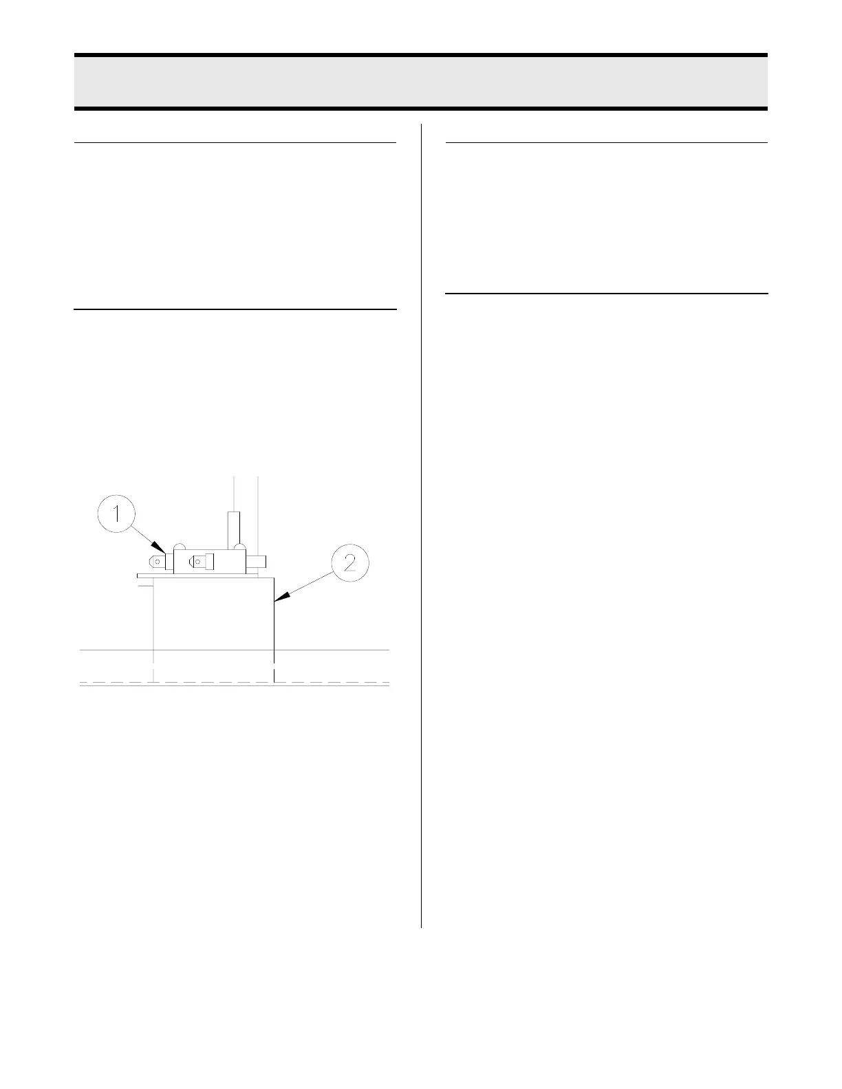
TIMER SWITCH
When the pressure regulating valve is
CLOSED, the timer switch initiates the tim-
ing circuit.
1. See ACCESS FOR SERVICE.
2. With needle nose pliers, disconnect
one wire from the switch (1).
3. CLOSE pressure regulating valve.
Check between remaining wire and
terminal where other wire was discon-
nected with an ohmmeter. Meter
should indicate a closed circuit. If not,
mounting bracket is out of adjustment
or switch is faulty.
Timer Switch Adjustment:
1. See ACCESS FOR SERVICE.
2. With pliers, bend mounting bracket (2)
closer or further away from control
rod.
Timer Switch Replacement:
1. See ACCESS FOR SERVICE.
2. Remove wires from switch.
3. Remove two mounting screws.
4. Install new switch in reverse order. Be
sure all wire connections are secure
and in their original location.
broaster.com Manual #17280 1/15 Rev 6/15