A-4
GF Series
Installation and Operation Manual
X-TMF-GF Series-MFC-eng
Part Number: 541B137AAG
March, 2010
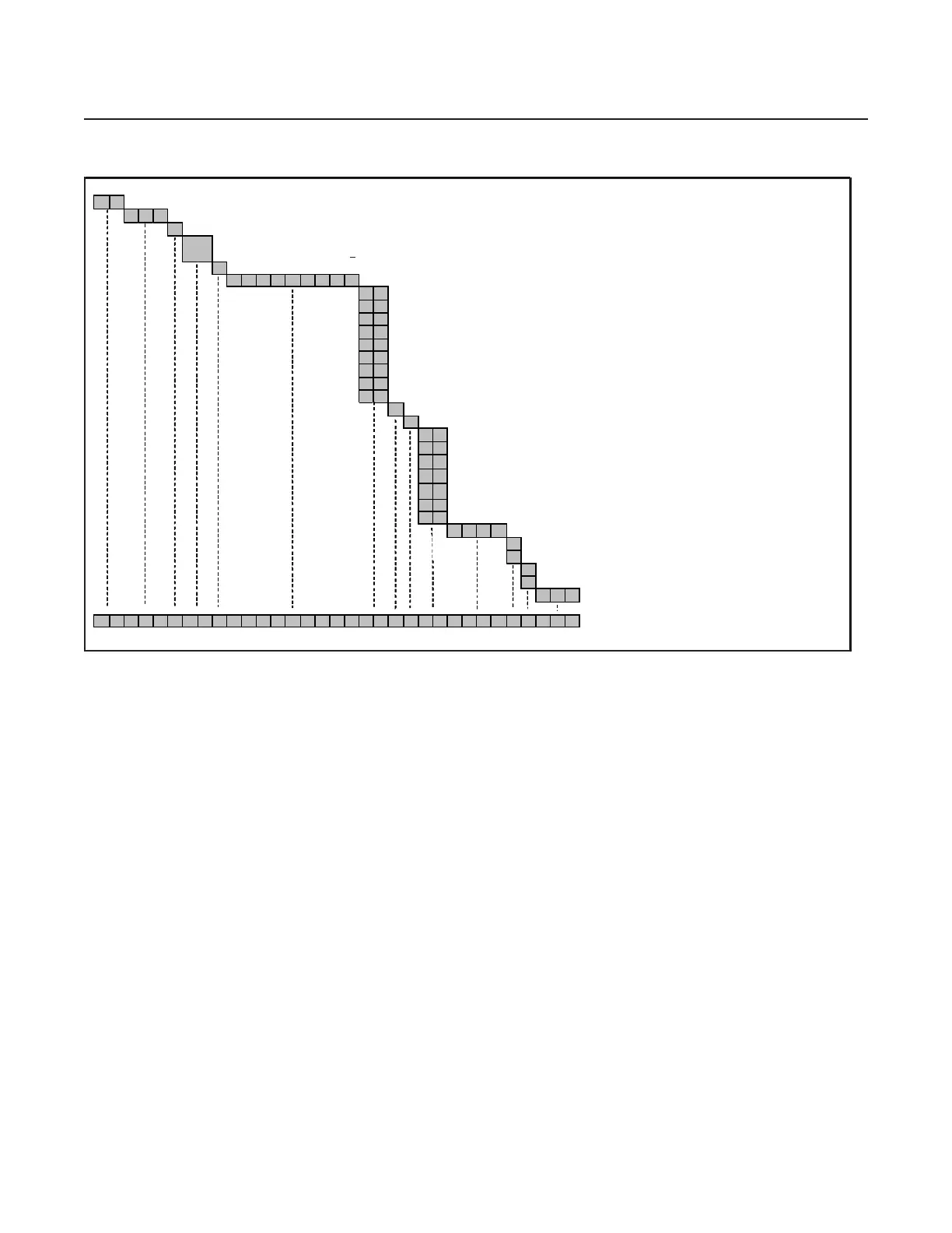
Appendix A: Product Description Code
GF
1 2 0 Flow Ranges from 2 sccm to 200 sccm N2 Euivalent
X Gas & Flow Specific
S D Safe Delivery, inlet Press. > 10 Torr; F.S. Flow 5-200 sccm
S L Safe Delivery, inlet Press. ? 10 Torr; F.S. Flow 4-25 sccm
CNormally Closed Valve
X X X X X X X X Specify Gas Code & Range, i.e. "0048" = BF3 and "010C" = 10 sccm
V X 1 1/2" VCR 1/4"
C X 1 1/8" C Seal 92mm
D X 1 1/8" C Seal 80mm
E X 1 1/2" W Seal 80mm
W X 1 1/8" W Seal 92mm
Y X 1 1/8 W Seal 80mm
A X 1 1/2" C Seal 92mm
B X 1 1/2" W Seal 92mm
L X 1 1/8" C Seal w/ Poke Yoke
V Vacuum - Default (If Atmosphere req'd, please contact Brooks Product Management)
O Standard Flow Sensor Orientation - Default
D X 5 pin DEVICENET micro (Unit "D", IN "D")
E X Cable adapter to Cardedge (w/out VTP), RS485 through RJ11 jacks
(Unit "E"; IN "L", "R"); display & overlay w/ 180
o
orientation
G X 9 pin D with RS485 (Unit "G"); display and overlay w/ 180
orientation
G 1 9 pin D with RS485 (Unit "G")
K X Cable adapter to MKS 15 pin D (Unit "K")
B B DeviceNet™ Analog (Not Available on 80mm fitting (DX, YX))
XXXX Customer Special Request Number
A Auto Shut Off, Enabled - Defaul t
X Auto Shut Off, Disabled
A
uto Zero, Enabled
X Auto Zero, Disabled - Default
0 0 0 0°C Reference Calibration (Standard) - Default
GF120XSDX- 0048010C-
X
G1-
XXX
X- 00 0
*example: BF3 , 10 sccm
Table A-4 GF120XSD-SL Product Description Code Table
<
 Loading...