iii
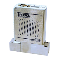
GF Series
Installation and Operation Manual
X-TMF-GF Series-MFC-eng
Part Number: 541B137AAG
March, 2010
Contents
Figure Figure
Number Number
1-1 GF1XX Series High Performance Gas Flow Controller Analog and Digital ................................... 1-1
2-1 GF1XX General Description.......................................................................................................... 2-1
2-2 GF1XX Operating Principles ......................................................................................................... 2-2
2-3 GF125 Side Can Label.................................................................................................................. 2-5
2-4 LED Display .................................................................................................................................. 2-7
3-1 Typical Gas Supply Arrangement with Non-PTI MFC.................................................................... 3-1
3-2 Typical Gas Supply Arrangement with PTI MFC ........................................................................... 3-1
3-3 GF1XX Mounting Attitude Positions .............................................................................................. 3-3
3-4 GF1XX Mounted to K1 Series Substrate Blocks ........................................................................... 3-4
3-5 Mounting Screws Torque Pattern .................................................................................................. 3-5
4-1 MultiFlo Cable Adapter .................................................................................................................. 4-1
4-2 RS-232/RS-485 Converter (P/N A3323000001)............................................................................ 4-1
4-3 Diagnostic Port .............................................................................................................................. 4-2
5-1 Display with PSI Reading .............................................................................................................. 5-2
5-2 Display Reading Zero PSI ............................................................................................................. 5-3
5-3 Display Set to %FS ....................................................................................................................... 5-3
5-4 %Flow Display Set to Zero ............................................................................................................ 5-3
D-1 GF1XX DeviceNet Connection......................................................................................................D-1
D-2 GF1XX with 9-Pin Analog Connector ............................................................................................D-2
D-3 Analog 9-Pin Connector (M) ..........................................................................................................D-2
D-4 DB9 to Open End Cable Adapter Assembly ..................................................................................D-3
D-5 DB9 to DB15, MKS Cable Adapter Assembly................................................................................D-3
D-6 DB9 to Card Edge Cable Adapter Assembly .................................................................................D-4
D-7 DB9 to DB15, UDU15 Cable Adapter Assembly............................................................................D-4
D-8 DeviceNet 1-1/8" C-Seal 92mm Downported ................................................................................D-5
D-9 Digital/Analog DB9, RS-485 1-1/8" C-Seal 92mm Downported ....................................................D-5
D-10 Digital/Analog DB9, RS-485 1-1/2" W-Seal 80mm Downported ...................................................D-6
D-11 DeviceNet 124mm 1/4" VCR Fittings ............................................................................................D-6
D-12 Digital/Analog DB9, RS-485 124mm 1/4" VCR Fittings.................................................................D-7
Table Table
Number Number
2-1 GF1XX Top Label.......................................................................................................................... 2-5
2-2 GF1XX Flow Range and Communication Protocols ..................................................................... 2-6
3-1 K1 Series Fasteners...................................................................................................................... 3-4
3-2 K1 Substrate Torque Data ............................................................................................................. 3-4
4-1 Gas and Flow Ranges - MultiFlo Configurable - N2 Equivalent .................................................... 4-2
7-1 Environmental Factors .................................................................................................................. 7-1
7-2 GF1XX Troubleshooting Guide ..................................................................................................... 7-2
A-1 GF125 Product Description Code Table ........................................................................................A-1
A-2 GF100 Product Description Code Table ........................................................................................A-2
A-3 GF120 Product Description Code Table ........................................................................................A-3
A-4 GF120120XSD-SL Product Description Code Table ..................................................................... A-4
B-1 Industry Standard References .......................................................................................................B-1
C-1 GF1XX Gas Table .........................................................................................................................C-1

 Loading...